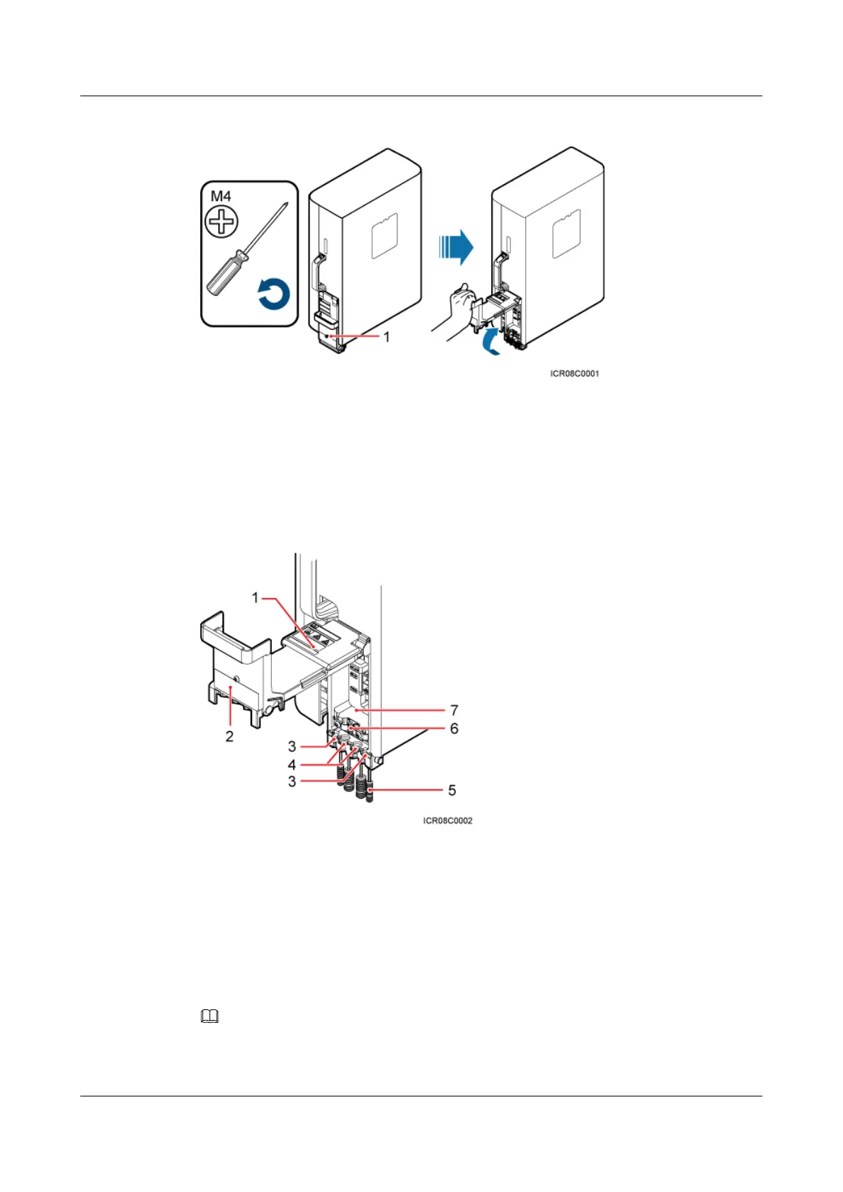
Figure 7-15 Opening the cover plate of the RRU cabling cavity
(1) Protection screw
Figure 7-16 shows the RRU cabling cavity.
Figure 7-16 RRU cabling cavity
(1) Cover plate
(2) Cable diagram on labels (3) Cable trough for the fiber optic cable
(4) Cable trough for the power cable (5) Waterproof block (6) Clip
(7) Cabling cavity - -
Step 3 Loosen the screws on the clip, and open the clip, as shown Figure 7-17.
NOTE
Open the clip only for the associated cable.
RRU3232
Installation Guide 7 Installing RRU Cables
Issue 05 (2011-10-20) Huawei Proprietary and Confidential
Copyright © Huawei Technologies Co., Ltd.
73
 Loading...