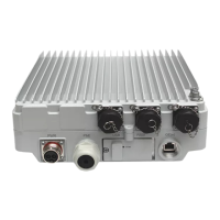
RRU3269
Installation Guide
Issue Draft B (2018-05-15)
Huawei Proprietary and Confidential
Copyright © Huawei Technologies Co., Ltd.
When installing CPRI optical fibers for single-fiber bidirectional optical modules,
remove the dustproof caps from the ports on the optical module and from the LC end
labeled 1A on the optical cable, divide the DLC end into two LC ends, and connect the
end labeled 1A to the optical module on the RRU side, as shown in Figure 9-28. Connect
the other LC end labeled 2A to the CPRI port on the main control board (such as the
GTMU) or baseband processing board (such as the WBBP) in the BBU.
Figure 9-28 Installing CPRI optical fibers for single-fiber bidirectional optical modules
Step 3 Route the cables according to the instructions in 9.1 Cabling Requirements.
Step 4 Label the installed fibers according to the instructions in Attaching an L-Shaped Label.
----End
9.11 Installing an RRU power cable
This section describes the procedure for installing an RRU power cable.
Prerequisites
A female connector (pressfit type) is added to the RRU power cable on the RRU side.
For details, see 12.1 Adding a Female Connector to the RRU Power Cable on the RRU
Side.
A connector is added to the RRU power cable on the power device side. For details, see
DBS3900 Installation Guide or DBS5900 Installation Guide.
Context
If a power device provided by the customer is used, the recommended specification of the
circuit breaker on this power device is 15 A to 30 A.
Table 9-2 describes RRU power cables.
 Loading...