Figures
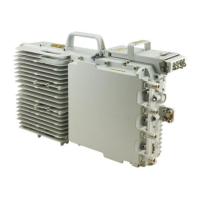
Figure 2-1 DC RRU............................................................................................................................................. 2-2
Figure 2-2 AC RRU............................................................................................................................................. 2-3
Figure 2-3 Panels of the DC RRU........................................................................................................................2-4
Figure 2-4 Panels of the AC RRU........................................................................................................................2-5
Figure 3-1 PGND cable........................................................................................................................................3-5
Figure 3-2 2-hole OT terminal............................................................................................................................. 3-5
Figure 3-3 Power cable for the DC RRU.............................................................................................................3-5
Figure 3-4 Power cable between the AC RRU and the external power equipment.............................................3-6
Figure 3-5 Power cable between the AC RRU and the AC surge protection box................................................3-7
Figure 3-6 Power cable between the AC surge protection box and the external power equipment.....................3-7
Figure 3-7 Monitoring signal cable of the AC RRU............................................................................................3-9
Figure 3-8 Multi-mode optical cable .................................................................................................................3-10
Figure 3-9 Single-mode optical cable................................................................................................................3-10
Figure 3-10 Alarm cable.....................................................................................................................................3-12
Figure 3-11 RF jumper.......................................................................................................................................3-13
Figure 3-12 Interconnect jumper........................................................................................................................3-13
Figure 3-13 AISG multi-wire cable....................................................................................................................3-14
Figure 3-14 AISG extension cable.....................................................................................................................3-15
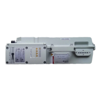
Figure 4-1 AC power surge protection box..........................................................................................................4-2
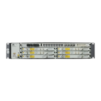
Figure 4-2 IFS06.................................................................................................................................................. 4-4
Figure 4-3 Structure of the IFS06.........................................................................................................................4-5
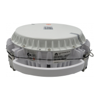
Figure 4-4 The application scenario of the OCB..................................................................................................4-6
RRU3908 V2
Hardware Description Figures
Issue 02 (2010-10-25) Huawei Proprietary and Confidential
Copyright © Huawei Technologies Co., Ltd.
ix
 Loading...