4 Circuit Breaker Control
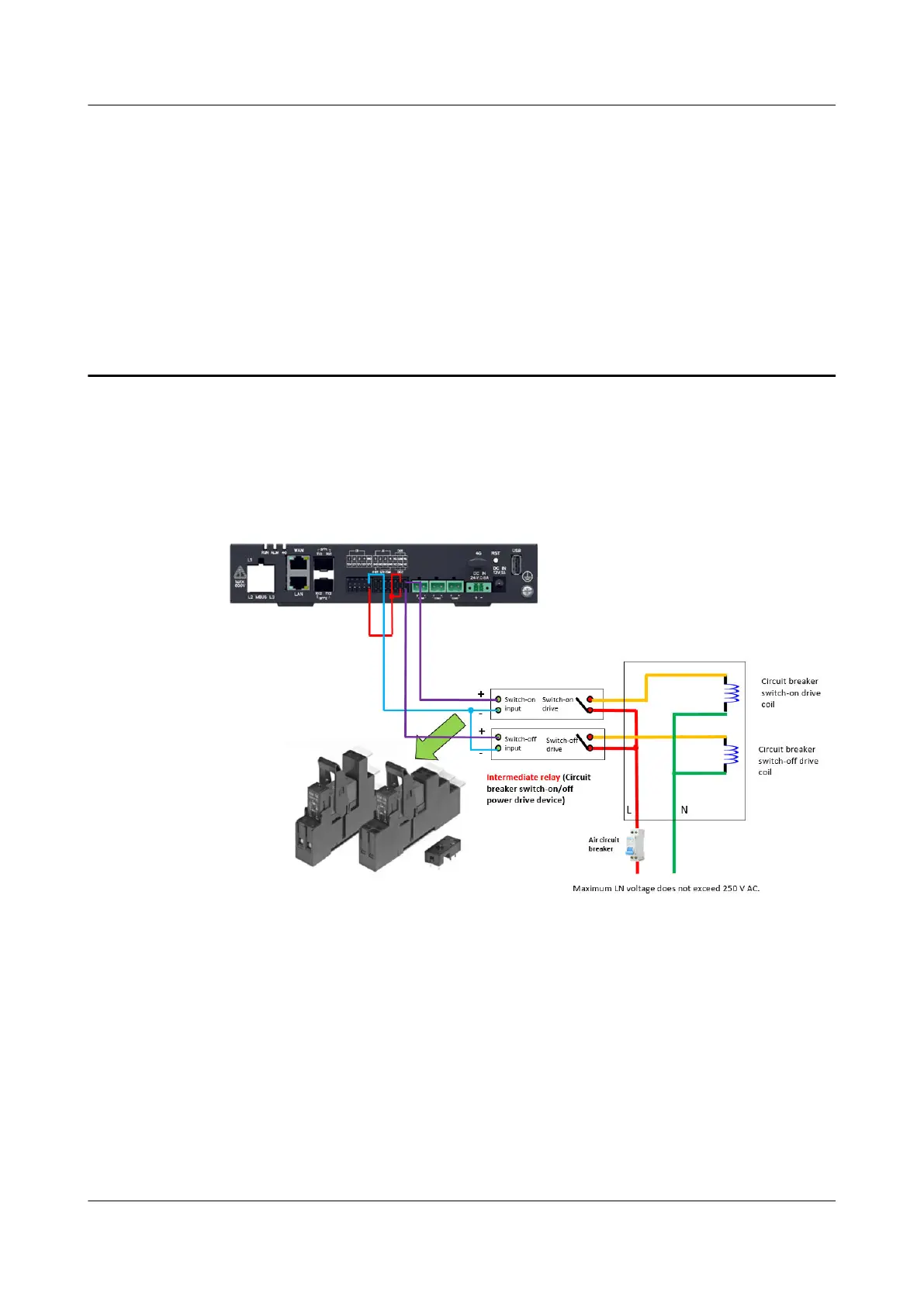
● The following gure shows the circuit breaker drive wiring diagram for the
SmartLogger1000A. DO1 is used as an example.
Figure 4-1
● DO1 on the SmartLogger3000 is used to control the switch-o output. The
NO port of DO1 is connected to relay +, and the COM port is connected to 12
V power supply +. The NO contact of the intermediate relay is connected to
the circuit breaker
switch-o coil.
● DI1 on the SmartLogger3000 is used to detect the switch-o status and is
connected to the circuit breaker
switch-o status output. DI2 is used to check
the switch-on status and is connected to the circuit breaker switch-on status
output. GND is connected to the common end of the circuit breaker.
● DO2 on the SmartLogger3000 is used to control the switch-on output. It is
wired in the same way as DO1. The
dierence is that the NO contact of the
intermediate relay is connected to the circuit breaker switch-on coil.
SmartLogger3000
Export Limitation Conguration Guide 4 Circuit Breaker Control
Issue 04 (2022-10-24) Copyright © Huawei Technologies Co., Ltd. 20
 Loading...

