10
2624 & 2630 Series Hydraulic Installation Tools (HK1052) Alcoa Fastening Systems & Rings
NOTE: When reassembling the tool, always replace damaged
and defecve parts, and all seals, wipers, O-rings, and Back-up
rings of subassemblies. Prior to reassembling the tool, HUCK
recommends having the following items accessible.
• The appropriate Huck Spare Parts Service Kit: P/N 2624KIT
(2624, 2624-15), P/N 2624HSKIT (2624HS, 2624-PT,
2624PTD), or P/N 2630KIT (2630, 2630RR)
• LUBRIPLATE® 130-AA (available as P/N 502723) or SUPER-O-
Lube® (available as P/N 505476)
BEFORE ASSEMBLING THE TOOL:
• Clean components in mineral spirits or other solvent
compable with O-ring seals.
• Clean out O-ring grooves.
• Inspect components for scoring, excessive wear, and
damage; replace as necessary.
• Replace O-rings and Back-up rings. See Assembly Drawings
for guidance on posioning these rings.
When assembling the tool, take care not to damage O-rings,
Quad-rings, Back-up rings.
• Smear LUBRIPLATE® 130-AA or SUPER-O-LUBE® on rings
and mang parts to ease assembly.
TO ASSEMBLE THE TOOL:
1. Assemble all seals,
washers, wipers, rings, and ejector rod into ejector gland/
cartridge. Hold the piston in a vise with so jaws and
install assembled ejector gland/cartridge assembly. Use
hex key (P/N 122048) to ghten.
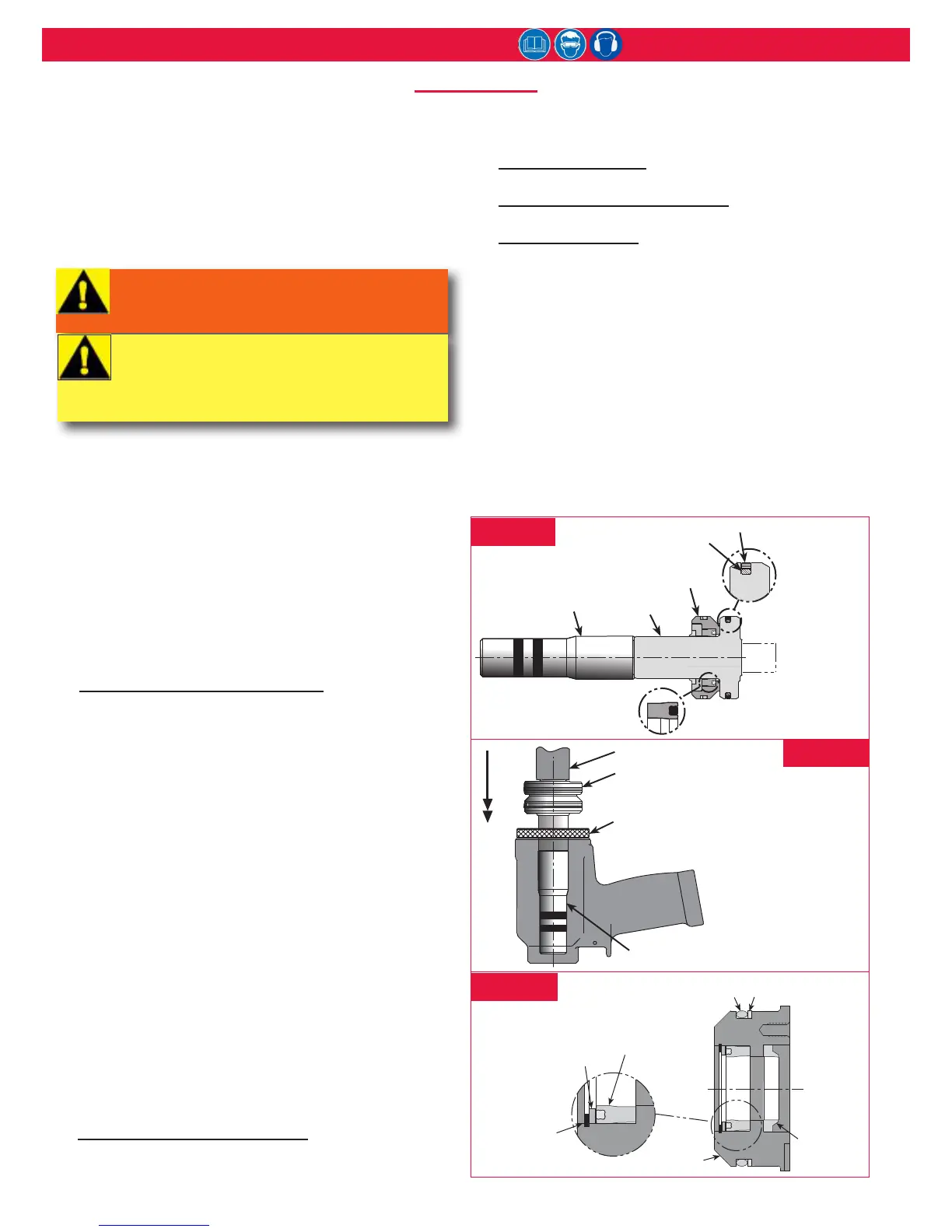
2. Thread the Piston Assembly Tool and GLYD ring onto the
piston (Figure 5). NOTE: Do not install the spacer. The
spacer is only used during disassembly procedure, as it
assists in pushing out the front gland assembly along
with the piston.
3. Install Polyseal, O-ring, Back-up ring, wiper housing, and
wiper into front gland. (Figure 5)
4. Lubricate the piston assembly tool and the piston; then
slide the assembled gland over the piston assembly tool
onto the piston. (Figure 5)
5. Thread the piston inseron tool into the back of the
cylinder. (Figure 6)
6. Using a press, push the piston and front gland assembly
into the back of the cylinder. (Figure 6)
7. Remove the piston assembly tool from the front of the
cylinder, and the piston inseron tool from the rear of it.
8. At the rear of the cylinder, install the dump valve (Figure
8) with the four ats facing the rear of the tool.
9. Install O-ring and Back-up ring on the end cap.
Install Back-up ring,
O-ring, wiper seal, Polyseal, washer, and retaining ring into
the end cap. (Figure 7)
10. Insert the hex key into the end cap. Use a wrench to
thread the end cap into the back of the cylinder and
ghten. (Figure 2)
11. Install locking disk, cover plate,
and retaining ring. (Figure 8)
Install locking disk,
retainer, and screws. (Fig. 9); 2624PTD see Fig. 10
: Install locking disk, clamshell
retainer assembly, and retaining ring. (Figure 11)
• If removed during disassembly, reinstall the electrical
connector. If the switch or wire was removed, replace
as follows: Slide the retaining nut and ferrule onto the
electrical wire. Feed the wire through the handle and pull
out through the trigger switch hole. Aach the wires to
trigger switch and push assembly back into the handle.
Tighten the setscrew to hold trigger switch in place. Slide
ferrule into the strain relief housing, then thread and
ghten the retaining nut.
• If removed during disassembly, install one hydraulic hose in
handle port marked “P” and one in port marked “R“.
• Install coupler nipple 110438 on PULL pressure side and
coupler body 110439 on RETURN pressure side of hoses.
asseMbly
2624HS
2624-PT
Piston
2624HS
2624-PT
Piston
2624HS
2624-PT
Piston
2624HS
2624-PT
Piston
2624HS
2624-PT
Piston
2624HS
2624-PT
Piston
2624HS
2624-PT
Piston
2624HS
2624-PT
Piston
2624HS
2624-PT
Piston
2624HS
2624-PT
Piston
2624HS
2624-PT
Piston
2624HS
2624-PT
Piston
2624HS
2624-PT
Piston
2624HS
2624-PT
Piston
2624HS
2624-PT
Piston
2624HS
2624-PT
Piston
2624HS
2624-PT
Piston
“special” O-Ring
123111-7 (2624 series)
123111-9 (2630 series)
fIgure 5
fIgure 6
WARNING: Do not omit any seals during
servicing; leaks will result and serious
personal injury can occur.
CAUTION: Do not use TEFLON
®
tape on
pipe threads. Tape can shred, resulting in
malfunctions. Apply Parker Threadmate,
Loctite 567, or Slic-tite stick to male pipe
threads per manufacturer’s instructions.
fIgure 7
 Loading...