7
2624 & 2630 Series Hydraulic Installation Tools (HK1052) Alcoa Fastening Systems & Rings
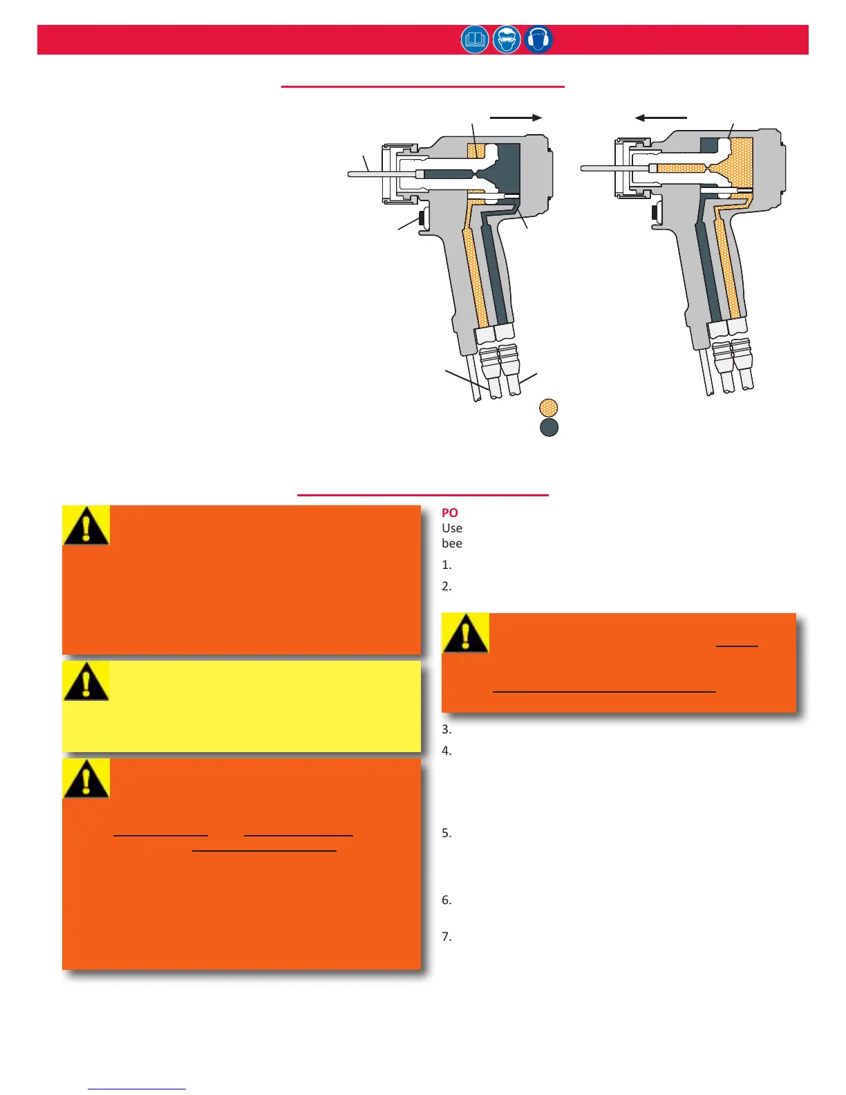
When the trigger is pressed, a solenoid-
operated valve in the POWERIG
®
directs
pressurized uid through the PULL hose to the
front side of the piston; uid on the RETURN
side ows back to the tank (Fig 1a). The piston
and nose assembly collet move rearward,
installing the fastener. When the piston
reaches the end of the PULL stroke, it uncovers
ats on the rear end of the dump valve. This
provides a passage for uid from the PULL side
to the RETURN side of the piston, “dumping”
the pressurized uid back to the tank (Fig 1a).
When the trigger is released, the solenoid is
de-energized and the valve directs pressurized
uid to the rear of the piston; uid on the
PULL side ows back to the tank (Fig. 1b). The
piston and collet move forward, and push
the nose assembly and tool o the installed
fastener. When the piston reaches the end of
the RETURN stroke, pressure builds, causing
the POWERIG to shut o, compleng the cycle.
prInCIple of operatIon
Threadmate is a registered trademark of Parker Intangibles LLC.
is a registered trademark of E. I. du Pont de Nemours and Co.
is a registered trademark of Henkel Corporaon, U.S.A.
is a registered trademark of LA-CO Industries, Inc.
POWER SOURCE CONNECTIONS
Use a Huck Powerig Hydraulic Unit, or equivalent, that has
been suitably prepared for operaon.
1. Turn OFF the Powerig and disconnect its power supply.
2. Coat the tool’s hose-ng threads with Locte
®
243
™
or
equivalent, and then connect the hoses to the Powerig.
3. Connect the tool’s control switch cord to the Powerig.
4. Connect the Powerig to the power supply and turn it ON.
Press and hold the tool trigger for 30 seconds; then press
trigger a few mes to cycle the tool and circulate the
hydraulic uid. Observe the acon of the tool and check
for leaks. Turn OFF the Powerig.
5. Disconnect tool’s control switch cord from the Powerig;
disconnect the Powerig from the power supply. Select a
nose assembly for the fastener to be installed and aach
it to the tool.
6. Reconnect the Powerig to the power supply and the
tool’s switch control cord to the Powerig.
7. Check the operaon of nose assembly; install fasteners
in a test plate of correct thickness with proper size holes.
Inspect installed fasteners.
NOTE: If fasteners do not pass inspecon, see
to invesgate possible causes.
preparatIon for use
WARNING:
Read entire manual before using tool.
A 30-minute training session with qualied
personnel is recommended before using Huck
equipment.
When operating Huck equipment, always wear
approved eye and hearing protection.
Be sure there is adequate clearance for the
operator’s hands before proceeding.
WARNING: Be sure to connect the tool’s
hydraulic hoses to the POWERIG before
connecting tool’s switch-control cord to the
POWERIG. If not connected in this order and
disconnected in the reverse order, severe
personal injury may occur.
CAUTION: Keep disconnected hoses and
couplers and hydraulic uid free of foreign
matter. Contaminated uid can cause valve
failures. Apply Parker Threadmate, Loctite
567, or Slic-tite stick to male pipe threads per
manufacturer’s instructions.
WARNING: Huck recommends that Huck
POWERIGS be used to power Huck tools.
Hydraulic power units that deliver high PULL
and RETURN pressures—but which are
NOT equipped with RELIEF VALVES—are
specically NOT RECOMMENDED and may be
dangerous.
Set the PULL and RETURN pressures as
specied in sPecIfIcatIons. Failure to properly
set these pressures may result in serious
personal injury.
Huck Pressure Gauge (P/N T-124883CE) is
available, and should be used as indicated in
its instruction manual.
 Loading...