9
2624 & 2630 Series Hydraulic Installation Tools (HK1052) Alcoa Fastening Systems & Rings
dIsasseMbly
This procedure is for complete disassembly of the tool.
Disassemble those components necessary to replace
damaged rings and worn or damaged components. Always
use a so-jaw vise to avoid damaging the tool.
1. Disconnect electrical or air connector from Powerig
®
.
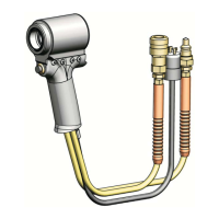
Uncouple tool hydraulic hoses.
2. Remove nose assembly.
3. Unscrew coupling nipple and coupling body. Drain
hydraulic hoses into container. Discard uid.
4. Push rearward on Piston unl remaining hydraulic uid is
drained into container. Discard uid.
NOTE: Do not remove hydraulic hoses from the tool unless
replacing the hoses. If it is necessary to remove hoses,
uncover the hose ngs by sliding back the plasc shrouds.
5. Use these steps only if the switch, wire, or electrical
connector needs repair. Remove retaining nut and locking
ferrule from strain relief. Loosen setscrew. Remove
trigger switch. Loosen and remove the two wires from
the switch. Remove cord from tool. Disassemble electrical
connector (P/N 110686).
6. Models 2624, 2624-15: Remove end cap retaining ring,
cover plate, and locking disk. (Figure 8)
Models 2624HS, 2624-PT, 2624PTD: Remove screws,
retainer, deector (2624PTD), and locking disk. (Figures 9
& 10)
Models 2630, 2630RR: Remove retaining ring from rear
of tool; then remove clamshell retainer assembly and
locking disk. (Figure 11)
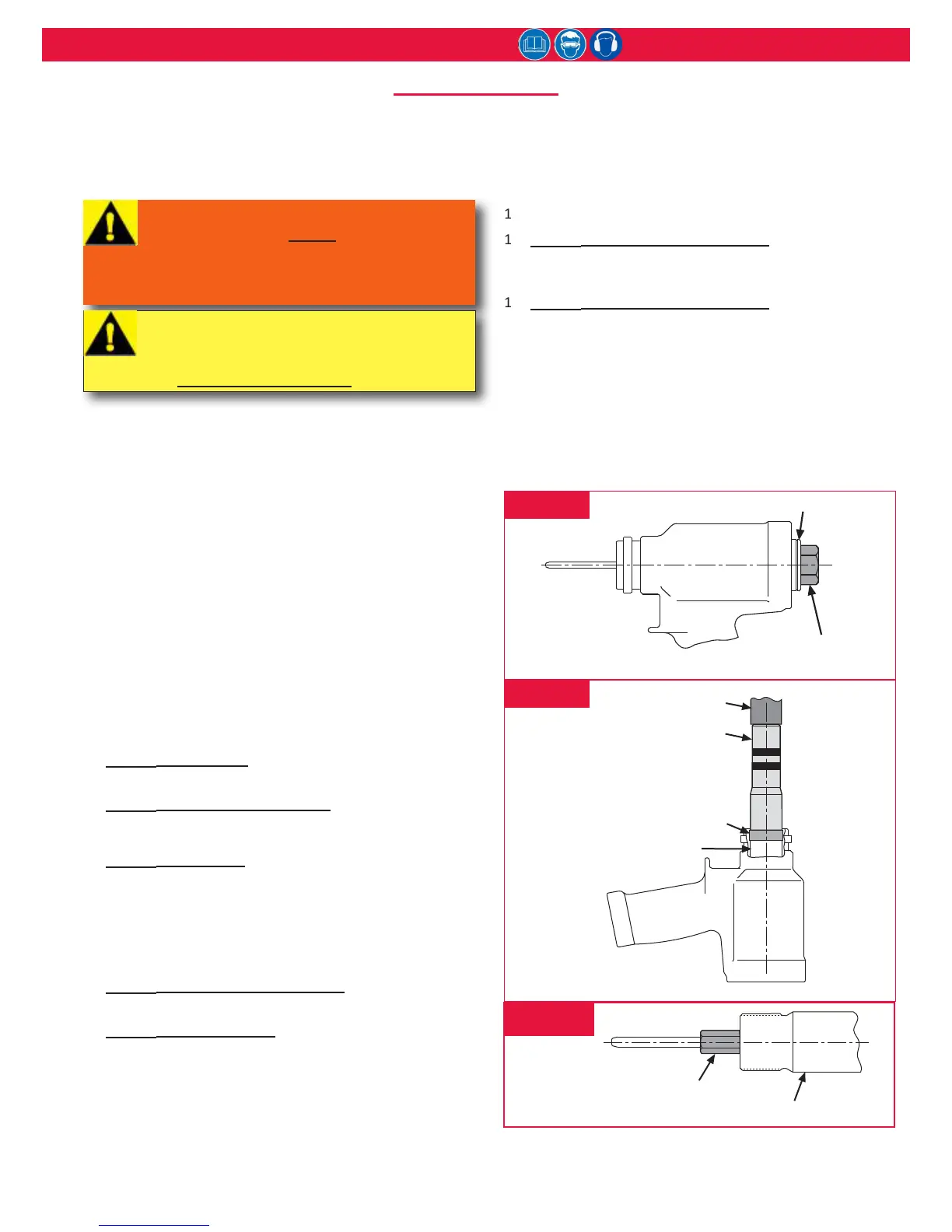
7. Insert hex key (P/N 126981, shipped with tool) into end
cap. (Figure 2) Using a wrench, unscrew the end cap from
the cylinder.
8. Models 2624, 2624-15, 2630, 2630RR: Remove the O-ring
and Back-up ring from end cap.
Models 2624HS, 2624-PTD: Remove the O-ring and Back-
up ring from front gland, and retaining ring, washer,
polyseal, and wiper seal from end cap.
9. Remove the dump valve from rear of cylinder.
10. Slide spacer over piston and thread Piston Assembly Tool
onto front of piston. Using a press, push front gland and
piston assemblies out the rear of the cylinder. (Figure 3)
11. Remove Piston Assembly Tool and spacer.
12. Slide front gland o of piston. Remove wiper, wiper
housing, Back-up ring, O-ring, and Polyseal from front
gland.
13. Remove the GLYD ring from the piston. (Figure 5)
14. Models 2624, 2624-15, 2630, 2630RR: Hold piston in a
vise and remove ejector gland/cartridge assembly with
hex key (P/N 122048). (Figure 4)
15. Models 2624, 2624-15, 2630, 2630RR: Remove ejector
rod, wiper, and all seals from gland/cartridge.
The tool has been properly disassembled. Store all re-usable
parts (screws and disassembled components) in a clean, dry
area.
fIgure 3
fIgure 4
fIgure 2
WARNING: Disconnect the tool control cord
from the POWERIG before disconnecting
the hydraulic hoses from it.
If not disconnected in this order, serious
personal injury may occur.
CAUTION: Do not re-use seals, wipers, or
rings; irreparable tool damage could occur.
Discard these parts and use replacements
(see sPare Parts servIce KIts).