16
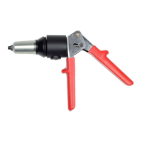
2624 & 2630 Series Hydraulic Installation Tools (HK1052) Alcoa Fastening Systems & Rings
troublesHootIng
1. Tool fails to operate when trigger is depressed.
a. Inoperative POWERIG® Hydraulic Unit. See
applicable instruction manual.
b. Loose air or electric connections.
c. Damaged trigger assembly.
d. Loose or faulty hydraulic hose couplings.
e. Unloading valve not installed in tool.
2. Tool operates in reverse.
a. Reversed hydraulic hose connections between
hydraulic unit and tool.
3. Toolleakshydraulicuid.
a. Defective tool O-rings or loose hose
connections at tool.
4. Hydrauliccouplersleakuid.
a. Damaged or worn O-rings in coupler body. See
Coupler 110440.
5. Hydraulicuidoverheats.
a. Hydraulic unit not operating properIy.
b. Unloading valve installed incorrectly.
c. POWERIG Hydraulic Unit running in reverse
(918: 918-5) See unit’s manual.
6. Tool operates erratically and fails to install
fastener properly.
a. Low or erratic hydraulic pressure; air in system.
b. Damaged or worn piston O-ring in tool.
c. Unloading valve installed incorrectly.
d. Excessive wear on sliding surfaces of tool
parts.
e. Excessive wear of unloading valve in tool.
7. Pull grooves on fastener pintail stripped during
PULL stroke.
a. Operator not sliding anvil completely onto
fastener pintail.
b. Incorrect fastener grip.
c. Worn or damaged jaw segments.
d. Metal particles in jaw segments pull grooves.
e. Excessive sheet gap.
8. Collar of HUCKBOLT® fastener not completely
swaged.
a. Improper tool operation. See Trouble 6.
b. Scored anvil.
9. Shear collar on Huck blind fastener not driven.
a. Improper tool operation.
b. Worn or damaged driving anviI in nose
assembly.
10. Tool “hangs-up” on swaged collar of
HUCKBOLT Fastener.
a. Improper tool operation. See Trouble 6.
b. RETURN pressure too low.
c. Nose assembly not installed correctly.
11. Pintail of fastener fails to break.
a. Improper tool operation. See Trouble 6.
b. Pull grooves on fastener are stripped. See
Trouble 7.
c. PULL pressure too low.
d. Worn unloading valve.
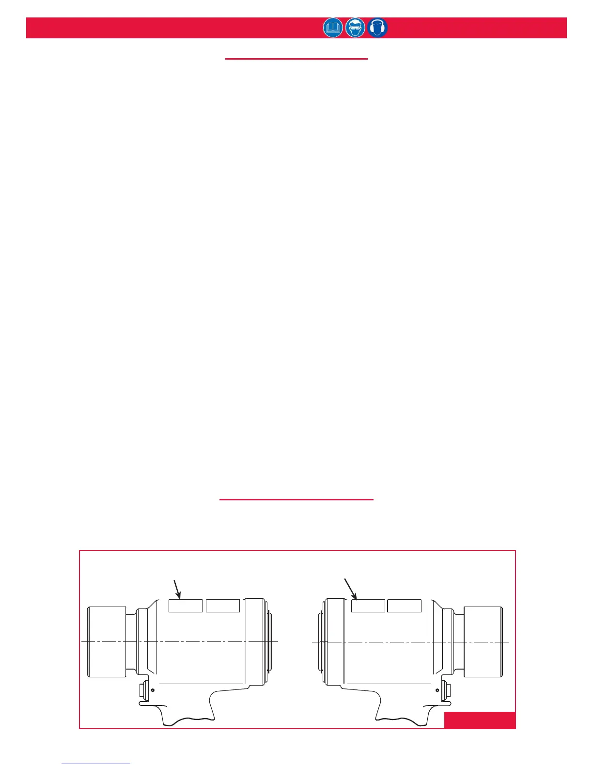
stICKer loCatIons
The 2600 Series tools are labeled with important stickers that contain safety and pressure-settings information.
These stickers must remain on the tools and be legible. Damaged, worn, and missing stickers must be replaced.
Sticker part numbers are shown below.
590512-5 CE & WARNING
Sticker (Maximum Operating Pressures)
590517 HUCK &
Year of Mfr Sticker
fIgure 15
Always check the simplest possible cause (such as a loose or disconnected trigger line) of a malfunction rst. Then
proceed logically, eliminating other possible causes until the cause is discovered. Where possible, substitute known
good parts for suspected defective parts. Use this Troubleshooting information to aid in locating and correcting
trouble.