507
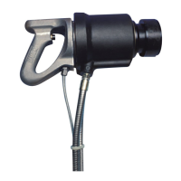
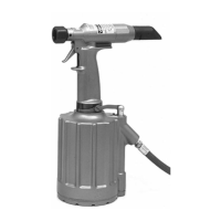
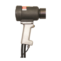
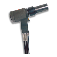
HYDRAULIC INSTALLATION TOOL
(HK480)
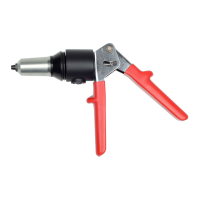
For component identification, refer to Figure 1.
Before assembling tool:
(a) Clean components In mineral spirits or other
solvent compatible With O-ring seals.
(b) Clean out O-Ring grooves.
(c) Inspect components for scoring, excessive wear or
damage.
(d) Replace O-Rings and back-up rings. Be sure that
relative positions of the O-Rings and back-up rings
are as shown in Figures.
(e) Specifications for O-Rings, back-up rings and
other standard components are shown in Table 5
so that they may be purchased locally.
(f) Smear Lubriplate 130AA on O-Rings and mating
surfaces to prevent damage to O-Rings and to aid
assembly.
WARNING: Do not omit any seals during
servicing, leaks will result and personal
injury may occur.
1. Press nose assembly adapter into Cylinder.
2. Place O-Ring and Washer into Ejector Cartridge.
Install Retaining Screw using 3/16 allen wrench.
Push pintail Ejector into Ejector Cartridge. Install
O-Ring and Back-up Ring on outside of Cartridge.
Screw Cartridge Assembly into Piston. Tighten
with 7/16 socket wrench. Note: Step 4 may be
done before assembling pintail Ejector and Ejector
Cartridge to Piston.
3. Place Piston Rod Guide P/N 102862 over the
threads of Piston rod and press Piston into
Cylinder and Adapter.
4. Place Relief Valve in hole in Piston.
5. Press Cylinder Cap into Cylinder so that the loca-
tor scallop in the cap matches the scallop in the
cylinder.
6. Place one Locator in matching scallops. (Cap can
be turned by putting a screw into one of the
tapped holes to use as a handle).
7. Screw Locking Ring into Cylinder using spanner
wrench.
8. Unscrew Locking Ring 1/4 turn or less until scallop
in Locking Ring matches scallop in Cylinder Cap.
Place Locator in matching scallops.
9. Position Cushion and Handle assembly in place
and assemble four Socket Head Screws and
Lockwashers. Tighten Screws to 490 inch pounds
torque if screws are plated and 655 inch pounds if
screws are unplated.
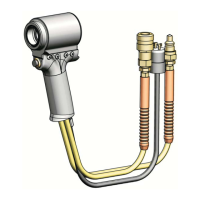
10. Screw Hoses into Cylinder. Coat hose fitting
threads with a non-hardening TEFLON
TM
.
CAUTION: Do not use TEFLON
®
tape on pipe
threads. Pipe threads may cause tape to
shred resulting in tool malfunction. (Slic-
Tite
TM
is available in stick form as Huck part
number 503237.)
11. Screw coupler Nipple onto Hose assembled into
cylinder PORT “P.”
12. Screw coupler Body onto Hose assembled into
cylinder PORT “R.” (Note: Tool will malfunction if
coupler Nipple and Body are not properly assem-
bled.)
13. Attach tool hoses to Powerig hoses and
actuate tool a few times to check operation
of tool and inspect for leaks caused by dam-
aged O-Rings.
14. Assemble Split Ring, Sleeve and Retaining Ring
when attaching the nose assembly.
Handle Assembly
1. Screw body of cord grip part of Strain Relief into
Handle.
2. Slide Strain Relief cap over cord.
3. Slide Strain Relief grommet over cord.
4. Place Cord in Handle so that leads come out the
Switch pocket.
5. Assemble leads to rear of Switch.
6. Push Switch into Handle and retain
with Set Screw.
7. Slide cover (not shown) over other end of Cord.
8. Assemble cap (two-prong plug) to Cord,
and slide cover over cap.
WARNING: Tool must be fully assembled
with all components included.