507
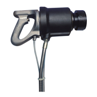
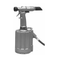
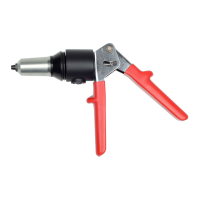
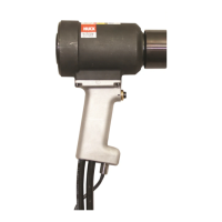
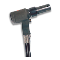
HYDRAULIC INSTALLATION TOOL
(HK480)
During disassembly and assembly, take the following
precautions to avoid damaging tool or components:
(a) Always work on a clean surface.
(b) Use relatively soft materials, such as brass, alu-
minum or wood, to protect tool when applying pres-
sure.
(c) Apply a continuous strong pressure, rather than
sharp blows, to disassemble or assemble a compo-
nent. An arbor press provides steady pressure to
press a component in or out.
(d) Never continue to force a component if it
“hangs.up” due to misalignment. Reverse the pro-
cedure to correct misalignment and start over.
(e) Smear Lubriplate 130AA
T.M
or equivalent, on O-
rings and mating surfaces to aid assembly and pre-
vent damage to O-rings.
(Lubriplate is a registered trademark of Fiske Brothers
Refining Co. A handy tube of Lubriplate 130AA is avail-
able from Huck as part number 502723).
A special Spanner Wrench, Part No. 110362, is avail-
able from Huck to aid in the disassembly and assem-
bly of Locking Ring, reference No. 11. Piston Rod
Guide Part No. 102862 are available to prevent dam-
age to piston rod seals when assembling the piston.
Standard hand tools such as wrenches, drifts, copper
or lead hammers, screwdrivers, socket screw hexagon
keys, long forceps (tweezers), etc. Which can be pur-
chased at most local supply firms are required. If pos-
sible, an arbor press and vise with soft jaws should be
available.
For component identification, refer to Figure 1.
The following procedure is for disassembly of Tool.
Remove one Locator Button and unscrew Locking
Ring using spanner wrench. Remove the second
Remove only those parts necessary. Check and
replace damaged/worn components. Always replace
O-rings, wipers, and back-up rings of disassem-
Screw Locking Ring part way in. Screw two Socket
Head Screws into Cylinder Cap. Use pry bars
under the heads of the screws to gradually pry
NOTE: Be sure POWERIG is turned “OFF” when
removing the nose assembly to clean or replace
Cylinder Cap out of Cylinder Assembly.
Remove Rnloading Valve.
components. See applicable Nose Assembly Data
Sheet for additional instructions.
Drain hydraulic fluid from Cylinder Assembly.
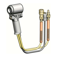
WARNING: Be sure to disconnect Tool’s
electrical control trigger system from
POWERIG® Hydraulic Unit BEFORE dis-
connecting Tool’s hydraulic hoses from
unit. If not disconnected in this order
before any maintenance or cleaning is
done, severe personal injury may occur.
1. Remove Retaining Ring from Split Ring, slide off
Sleeve and remove Split Ring segments. Pull nose
assembly anvil off and unscrew nose collet assem-
bly.
2. Remove four Socket Head Screws and
Lockwashers from Handle. Handle Assembly and
Cushion are now separated from the Tool.
7. Unscrew Hoses.
8. Press Piston out of CylinderAssembly. Use an
arbor press if one is available.
9. Unscrew Ejector Cartridge Assembly using 7/16
socket wrench. Slide Ejector out of cartridge
assembly. Unscrew Retaining Screw from cartridge
assembly using 3/16 allen wrench.
10. Remove Retaining Ring.
11. Press Adapter out of Cylinder Assembly.
12. Use a small dull-pointed rod to remove O-Rings
and Back-up Rings from all components.