507
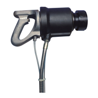
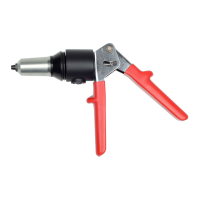
HYDRAULIC INSTALLATION TOOL
(HK480)
WARNING: Huck recommends that only
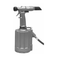
Huck Powerig Hydraulic Units be used
as a power source for Huck installation
equipment. Hydraulic power units that
deliver high pressure for both PULL and
RETURN, AND ARE NOT EQUIPPED
WITH RELIEF VALVES ARE SPECIFICAL-
LY NOT RECOMMENDED AND MAY BE
DANGEROUS.
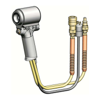
When tool hoses and cord are connected to Powerig hoses
and control cord, PULL and RETURN strokes of tool are con‐
trolled by a Trigger in the handle.
When the trigger is depressed, a solenoid operated valve in
the POWERIG directs pressured fluid through the FILL
Hydraulic Hose to the front side of piston, and allows fluid
on the RETURN side to flow back to tank.
The piston and nose assembly collet moves rearward caus‐
ing follower O‐rings and/or spring to impart a forward
motion to the follower.
If tool and nose assembly is in position on a fastener pin
and collar, this forward motion causes the jaws to clamp
onto pintail of fastener and installation cycle commences.
Clamping pressure is applied to the sheets. The anvil is
forced forward, swaging the collar into locking grooves of
the fastener.
When the anvil hits the sheet, continued pull causes the
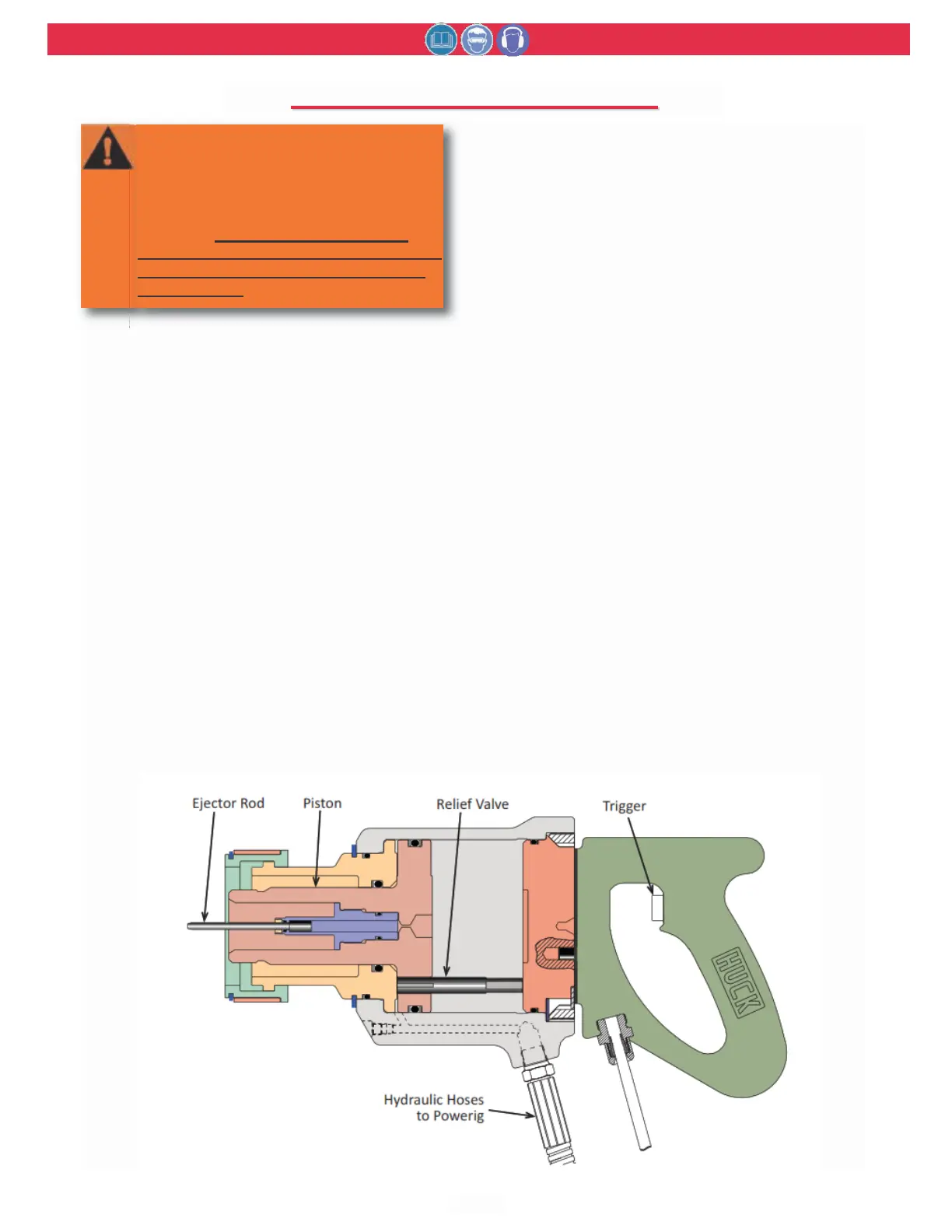
pintail to break off. When the Piston reaches the end of its
PULL stroke, it uncovers flats on the rear end of the Relief
Valve. These flats were designed to provide a passage for
hydraulic fluid from PULL side to RETURN side of piston,
“unloading” or “dumping” the pressurized fluid back to
tank.
When the trigger is released, the solenoid is de‐energized
and the valve directs pressurized fluid to rear side of the
piston and allows fluid on PULL side to flow back to tank.
This causes piston and collet to move forward and pushes
nose assembly and tool off the swaged (installed) fastener.
Nose assembly jaw release contacts jaws, causing them to
open and release the broken‐off pintail. The Ejector Rod
hydraulically ejects the pintail out the front of the nose
assembly. When the piston reaches the end of its RETURN
stroke, pressure is built up causing the Powerig idler valve
(except on Models 910 and 911) to go to idling pressure.
Idling pressure keeps the tool piston and nose assembly
collet, jaws, etc. in the forward position ready for the next
installation cycle.
A flat on the front end of the relief valve was designed to
provide a passage for hydraulic fluid from RETURN side of
piston to PULL side of piston and back to tank.