15
• In the I-Core controller, the terminals are marked
either S1 (one is red, and one is black) or S2 (or
S3 in metal versions).
When used with a Hunter ICD-SEN sensor
decoder, consult the manual for the ICD-SEN.
• Flow-Sync may only be used on Port A of a
sensor decoder.
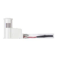
• Cut the purple loop (Port A) on the sensor
decoder.
• Observe polarity-when the loop is cut, the lead
on the station label side of the ICD-SEN is the
negative (-) side.
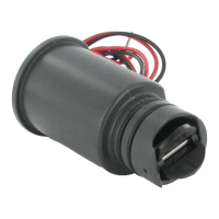
• Connect the black wire from Flow-Sync to the
negative side of the decoder port, and connect
the red wire to the positive side of the port.
• Finish configuration as described in the
ICD-SEN and ACC controller documentation.
Note: The Flow-Sync Sensor can be
installed up to a maximum of 1,000
ft/300 m from the controller when
installed with 18 AWG or 1 mm gauge
or larger copper wire.