41865-01 01/15/2007 © 2007 Hunter Fan Company
8
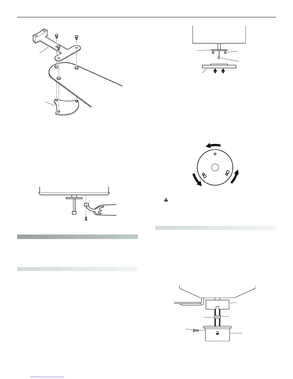
Figure 24 - Attaching the blade to the blade iron and
medallion
If you used grommets, the blades may appear slightly loose
after screws are tightened. is is normal.
3. Remove the blade mounting screws and rubber shipping
bumpers from the motor.
4. For each blade, insert one blade mounting screw through the
blade iron as shown in Figure 25, and attach lightly to the fan.
Insert the second blade mounting screw, then securely tighten
both mounting screws.
Figure 25 - Attaching the blade iron to the fan
installing the light xture
You can install with or without the light fixture. If you want to
install without the light fixture, skip to the installing without the
light fixture section.
attaching the upper switch housing
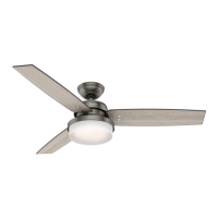
1. Partially install two #6-32 x 3/8” housing assembly screws into
the switch housing mounting plate as shown in Figure 26.
2. Feed the upper plug connector through the center opening of
the upper switch housing. See Figure 26.
Figure 26 - Attaching the upper switch housing to the
mounting plate
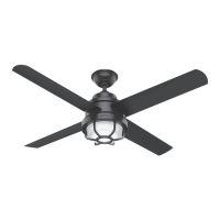
3. Align the keyhole slots in the upper switch housing with the
housing assembly screws installed previously.
4. Turn the upper switch housing counterclockwise until the hous-
ing assembly screws are firmly situated in the narrow end of the
keyhole slots as shown in Figure 27. Install the one remaining
#6-32 x 3/8” housing assembly screw into the third hole in the
upper switch housing. Tighten all three screws firmly.
Figure 27 - Mounting the upper switch housing
CAUTION: Make sure the upper switch housing is
securely attached to the switch housing mounting plate.
Failure to properly attach and tighten all three housing
assembly screws could result in the switch housing and
light fixture falling.
attaching the lower switch housing
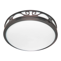
1. Connect the upper plug connector from the motor to the
lower plug connector in the lower switch housing assembly.
See Figure 28.
NOTE: Both plug connectors are polarized and will only fit
together one way. Make sure that both connectors are properly
aligned before connecting them together. Incorrect connection
could cause improper operation and damage to the product.
Figure 28 - Connecting the plug connectors
Blade Iron
Medallion
Switch Housing
Mounting Plate
Upper Switch
Housing
Housing
Assembly
Screw
Upper Plug
Connector
Lower Plug
Connector
Upper Switch
Housing
Upper Plug
Connector
Lower
Switch
Housing
Housing
Assembly
Screw