Instrument-Computer Ground Potential Check:
Perform this check if the power cord wiring is being changed, such as for replacement of the
cord or if changing the plug.
The instrument serial port ground connection is referenced to the instrument’s internal frame
and safety ground. Before connecting the communication cable to the instrument serial port,
apply power to the instrument and the host computer. Check the ground potential (voltage)
between the serial port ground pins on the computer and the instrument. The ground
connection is pin 5 on DB-9 connectors and pin 7 on DB-25 connectors. Voltages in excess of
5VAC at 110V input power, or in excess of 10VAC at 220V input power may indicate a difference
in ground wiring and can damage the instrument and/or the computer. Check the wiring and
take other steps as needed to reduce this difference before connecting the communications
cable. You may also use a data optoisolator.
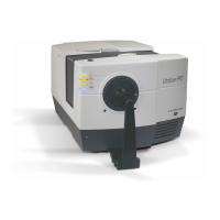
Conditions of Illumination and Viewing
0° from normal via a circumferential fiber optic ring degree
illumination; 45° from normal via a 15-station circumferential fiber
optic ring
50 mm (2.0 in) / 44 mm (1.75 in)
30 mm (1.2 in) / 25 mm (1.0 in)
17 mm (0.7 in) / 13 mm (0.5 in)
10 mm (0.4 in) / 6 mm (0.25 in)
5 mm (0.2 in) / 3 mm (0.13 in)