3
34
502 50 18-01
502 50 18-01
Fuel system
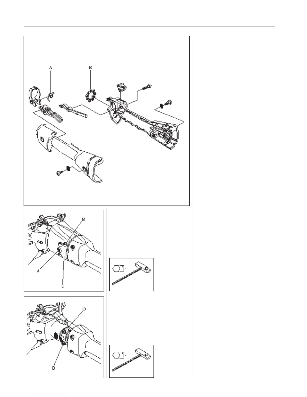
Assembly of the throttle is done in the
reverse order as set out for dismantling.
Position the parts in the left-hand throttle
half.
Ensure the return spring (A) is facing the
right way.
Check that the throttle cable and the
short-circuit cable are pressed correctly
down in their channels so that they are not
pinched when the two throttle halves are
screwed together.
Do not forget to put the vibration element
(B) in position before the throttle halves
are put together. Lubricate the vibration
element with soapy water. This facilitates
tting the throttle on the shaft.
Fit together the throttle halves using the
5 screws, but do not tighten them fully
before the throttle has been positioned on
the shaft.
Assemble the remaining parts in the re-
verse order as set out for dismantling.
Throttle, model 327
Separate the engine body and the
clutch cover.
Remove the screws (A) and (B).
Lift o the covers (C).
Throttle, model 327
We recommend that the throttle is dis-
mantled from the engine and shaft in order
to e ciently carry out service and repair
work.
Separate the engine body and the clutch
cover (see chapter ”Ignition system”).
Remove both screws (A) (one on each
side).
Remove the screw (B) and lift o the
cover (C).
Unscrew the screws (D).
Remove the clutch cover and the throttle
handle from the shaft.
Loosen the screws (D) holding the are
tting around the shaft.
Remove the clutch cover and the throttle
handle from the shaft.