3
35
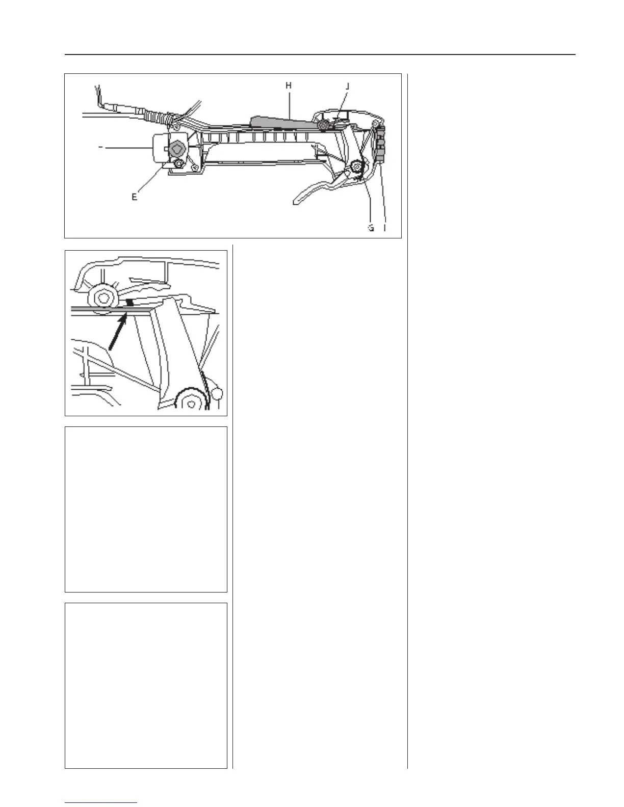
Fuel system
Remove the 5 screws holding the handle
in place.
Carefully remove the right handle half and
make sure that the vibration damper (E) is
not lost (one on each side of the clamping
sleeve).
Note how the di erent parts are tted.
Remove the clamping sleeve (F).
Note how the throttle’s recoil spring (G) is
tted and remove the throttle lever.
Remove the throttle trigger lock (H) and
the vibration element (I).
Assemble in the reverse order as set out
for dismantling. Do not forget to put the
vibration dampers (E) and (I) in place.
Check that the throttle cable is tted to
the underside of the pin (J) on the throttle
trigger lock.
See also the “Throttle, model 326” assem-
bly section.
Check that the throttle cable is tted to
the underside of the pin (J) on the throttle
trigger lock.
See also the “Throttle, model 326” assem-
bly section.