1
2
3
4
5
6 7
Main menu
Commands
Timer
Garden
Settings
GETTI NG STARTED
WITH HUSQVARNA AUTOMOWE R
®
3
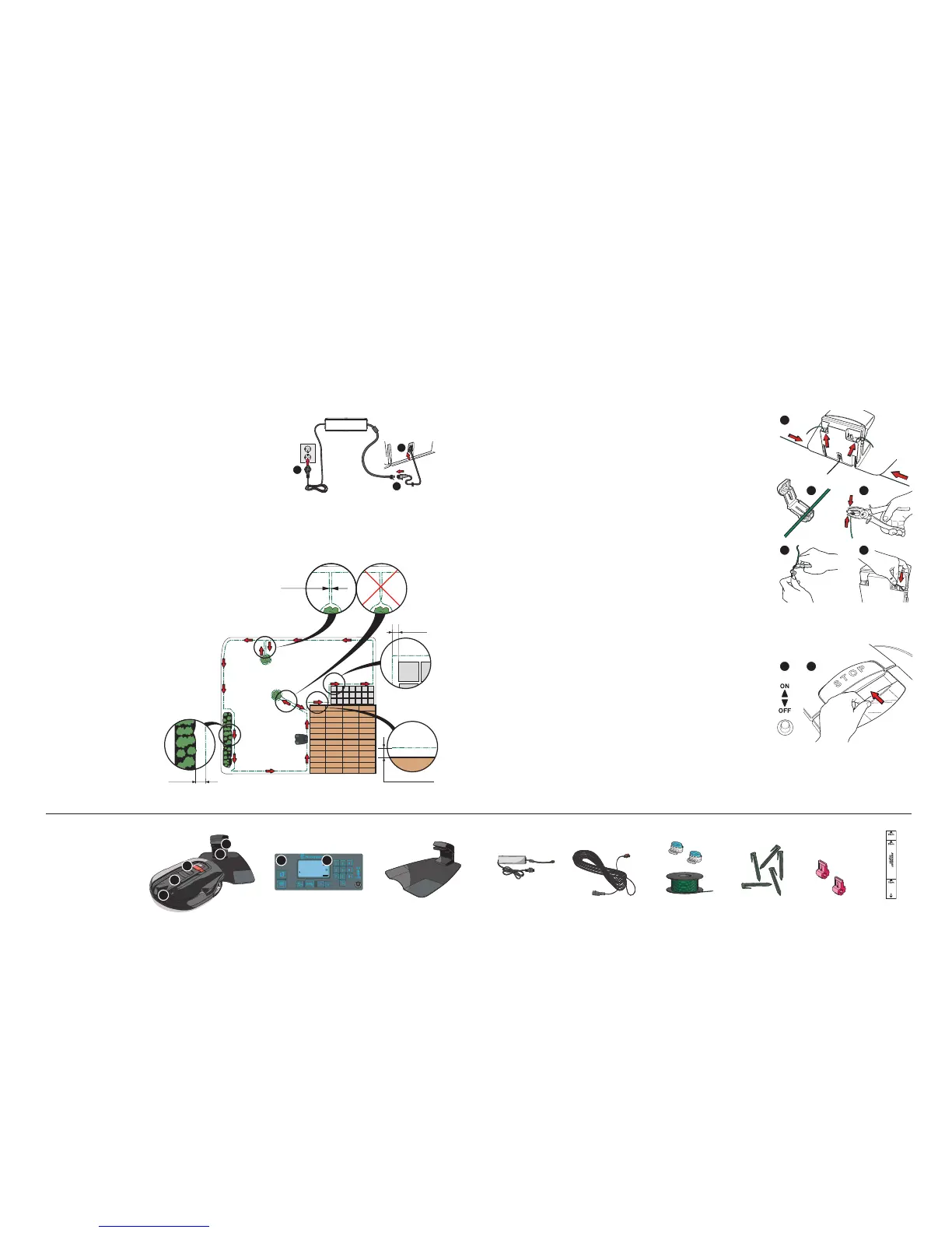
1. Lift off the cover on the charging station and push in the
ends of the boundary wire in the lower holes of the
charging station and catch them in the upper holes:
• Right wire end in right hole.
• Left cable end in left hole.
2. Open the connector and run the wire ends in the recesses
on each connector.
3. Press the connector together using a pair of pliers.
4. Cut off any surplus boundary wire.
Cut 1-2 cm / 0.5-0.78" above the connector.
5. Press the connector onto the contact pin,
marked A, on the charging station.
Ret the cover on the charging station.
1
2
4
STARTI NG AND STOPPING AUTOM OWER
®
See chapters 3.7, 4.4 and 4.5 in the Operator’s Manual.
PLACE ME NT AND CONN ECTI NG THE CHA RGIN G STATION
See chapter 3.2 in the Operator’s Manual
CH ARGI NG THE BATTERY A ND PLACING THE
BOUN DARY WI RE
See chapters 3.3 and 3.4 in the Operator’s Manual.
1. Place the charging station centrally in the work area,
leaving a lot of free space in front of the charging station
and on a relatively horizontal surface.
2. Connect the low voltage cable to the charging station and
transformer.
3. Connect the transformer’s power cord to an electrical wall
socket. The 120 V transformer (USA) is for indoor use only.
1. Place Automower
®
in the charging station to
charge the battery while you are laying the
boundary wire. Set the main switch to
the OFF position.
2. Run the boundary wire ensuring it
forms a loop around the work area.
STARTING
1. Open the control panel cover by pressing the STOP button.
2. Set the main switch to ON position. When you do this for
the rst time, a start up sequence starts where you select a
four digit PIN code among other things. The mower must
be in the charging station when you select a PIN code.
3. Close the cover.
STOPPING
Press the STOP button.
Charging station Transformer Low voltage cable Boundary wire *
and connector
Pegs * Connector Measurement gauge
CON NEC TING TH E BOUNDARY W IRE
See chapter 3.5 in the Operator’s Manual
1
4 5
32
32
1. Charging strip
2. Latch button to open the cutting
height adjustment cover
3. STOP button
4. LED for performance inspection
of boundary wire
5. Contact strips
6. Keypad
7. Display
* Not included in package

 Loading...