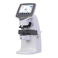
3. Loose and take out the screws in Upper Holes.
4. Loose the Socket Set Screws.
5. Lift up the Pinhole Housing and replace it the new one.
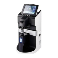
6. Turn on the machine to the Setup Mode and then press ‘LENS’ (Key 1) button for a
while to go into the Calibration Display.
7. Press the first ‘ALIGN’ button to see the position information.
8. Rotate the Pinhole Housing a little to make the parallel level which is the sum of two
A12 less than |0.1|.
9. Fasten the 5 Socket Set Screws keeping the parallel level guaranteed.
10. Fasten all the screws in Upper Holes.
11. Place the Upper Cover of Pinhole Housing and stick it.
12. You must execute all procedures for the calibration that are described in from the
section 2.2 to section 2.6.
 Loading...