10
amount of concrete used to form the pad should exceed
the weight of the compressor by 3 to 5 times. SAE Gr.
5 “J” bolting of appropriate length and size should be
used in the pad to provide baseplate mounting. Use of
a template to support and position the bolting +/– 1/16”
while setting concrete is recommended. Securing
bolting to existing foundations with drilled holes and
adhesives is not recommended unless expert advice
is available. Expert advice is also recommended for
installation of other forms of mechanical anchors. See
Figure 3 for additional details.
Epoxy based grouting is required to firmly seat
and attach the compressor skid to the concrete
foundation. ITW Philadelphia Resins brand “Chockfast
Red” grout is recommended. Sealing of grouts and
concrete is recommended to prevent contamination
by oil and moisture. Newly poured concrete must be
fully hydrated prior to grouting. The concrete slab
should be chipped to remove all latent and 50% of
the aggregate exposed to provide a rough bonding
surface for the epoxy. Dowels should be installed on
new exposed concrete to prevent edge lifting. The
concrete foundation should be dry and free of oil before
pouring grout. Sleeve all foundation bolts to prevent
adhesion and allow bolt stretch. Steel baseplates
should be sanded and cleaned to provide adequate
adhesion surface.
Steel fabricated foundations must be adequately
engineered to support the weight and vibration of the
compressor.
INLET PIPING & INLET FILTRATION
Compressor life can be substantially increased by
providing clean, dry, cool gas to the compressor
inlet.
Ambient Air Compressors – In most cases,
the standard air fi lter furnished from the factory is
suffi ciently large to meet normal operating conditions
when periodically serviced. Where the compressor
inlet is to be piped to the outside, a hood or shroud
must be installed to prevent rain from entering the fi lter
or pipe. In severe environmental conditions, it may
be necessary to consider a non-standard inlet fi lter.
Contact the factory for assistance in this case.
Large runs of intake piping require an increase in
piping size to maintain compressor effi ciency; pipe
size should be increased one size for each 10 feet of
intake pipe and each 90° bend.
Air Boosters & Gas Compressors – The inlet piping
may be at a pressure above atmospheric, and must
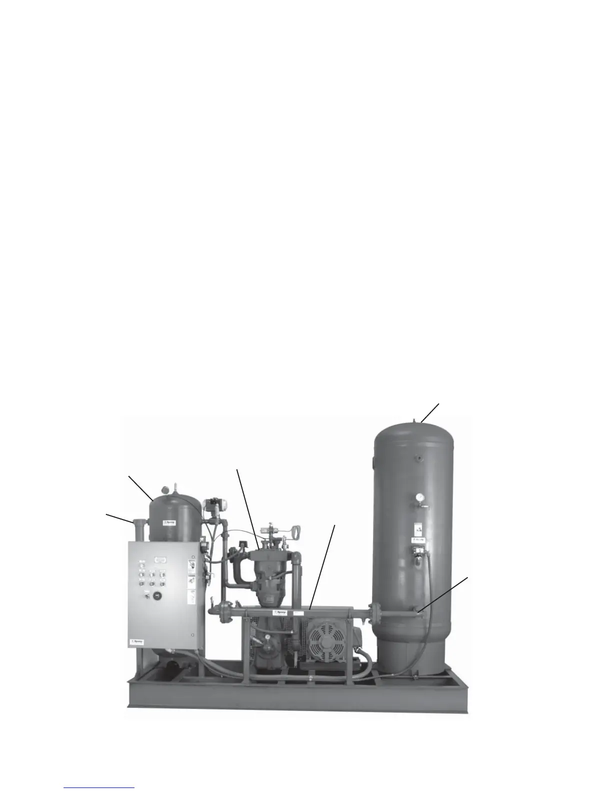
Inlet Receiver
Inlet Filter
(required on all
applications)
Hycomp Booster
Compressor
Discharge Receiver
Discharge
Check Valve
(required on all
applications)
Aftercooler
Figure 4: Basic System Confi guration of an Air Booster or Gas Compressor