28
5. Install a new oil filter. Reassemble control
components. Components will have to be
mounted 180 degrees from previous positions.
6. Double check the rotational arrows. Start the
compressor and check the oil pressure.
7. On air cooled units, replace the standard sheave
with a reverse rotation sheave.
‘V’ BELT TENSION AND
ALIGNMENT SETTINGS
Improper pulley alignment and belt tension will cause
motor overload, excessive vibration, and premature
belt and bearing failure. The belt must be routinely
inspected for cracks, burns, frays, or any unusual wear
and replaced if necessary. Routinely check the motor
sheave and compressor fl ywheel for oil, grease, or
burrs. Clean or replace when necessary. Make sure
all mountings are securely fastened. The drive belt
grooves of the sheave and fl ywheel must line up with
each other. The motor drive shaft must be parallel
to the compressor crankshaft. Hycomp recommends
banded belts rather than multiple individual belts.
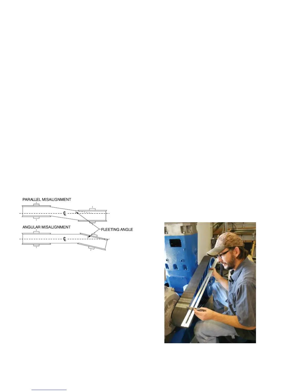
The following diagrams describe types of misalign-
ment:
the method below. Alignment on V-belt drives should
be less than 1/2˚ or 1/10” per foot of center to center
distance.
Straight Edge Method - This method can be used to
align the motor sheave and compressor fl ywheel.
1. Confi rm that the compressor, motor and motor mount
are squared up with the skid face and all mounting
bolts are secure.
2. Install bushing and sheave on the motor shaft.
3. Place the belt(s) on the motor sheave and
compressor fl ywheel and temporarily tighten belt by
adjusting the motor base mount. Note: Banded V-belts
may need to be installed at the same time as the motor
sheave for ease of assembly.
4. Place a straight edge across the face of the
compressor fl ywheel, spanning the motor sheave. An
angular misalignment will be observed as an angle
between the straight edge and the face of the motor
sheave. A parallel misalignment will be observed as an
offset between the center line of a belt on the fl ywheel
and motor sheave. Resolve angular misalignment
prior to making corrections in parallel misalignment,
as angular corrections require repositioning of the
motor.
Alignment Evaluation - (see fi gure 19b)
Angular Alignment: Place a straight edge across the
compressor fl ywheel with the loose end of the straight
Figure 19a: Misalignment
Figure 19b: Alignment Evaluation
Angular Misalignment - The motor shaft and
Compressor crankshaft are not parallel. This is typically
due to an alignment error at motor or motor adjusting
base. Correct alignment by shifting the motor to bring
the motor shaft parallel with the crankshaft.
Parallel Misalignment - The sheave is not properly
located on the motor shaft. This is typically caused
by improper location of the motor drive sheave on
the motor shaft. Loosen and reposition sheave until
properly aligned with fl ywheel.
Sheave Wobbling on Shaft - Sheave or bushing not
installed on motor shaft correctly.
Note: Sheave alignment can be checked by using