29
Plunger with
Defl ection force
scale (lbs)
Small “O”-ring
Body with Defl ection
Scale (inches)
Large
“O”-ring
Figure 19d: ‘V’ Belt Tension Gauge
edge not in contact with the motor sheave. Observe
alignment of the face of the motor sheave with the line
of the straight edge. Adjustment of the motor and/or
mounting base will be required to correct angular
alignment.
Parallel Alignment: Place a straight edge across the
compressor fl ywheel with the loose end of the straight
edge not in contact with the motor sheave. Place a
straight edge across the compressor fl ywheel with
the loose end of the straight edge not in contact with
the motor sheave. Measure from straight edge to a
marked reference point on the belt at the fl ywheel.
Rotate belt to shift the marked reference point at the
motor sheave. Adjust sheave on motor shaft to obtain
equal measurements.
The belt can now be tightened via the motor base,
refer to specifi c V-belt manufacturer tension ratings.
An example of defl ection force tensioning follows:
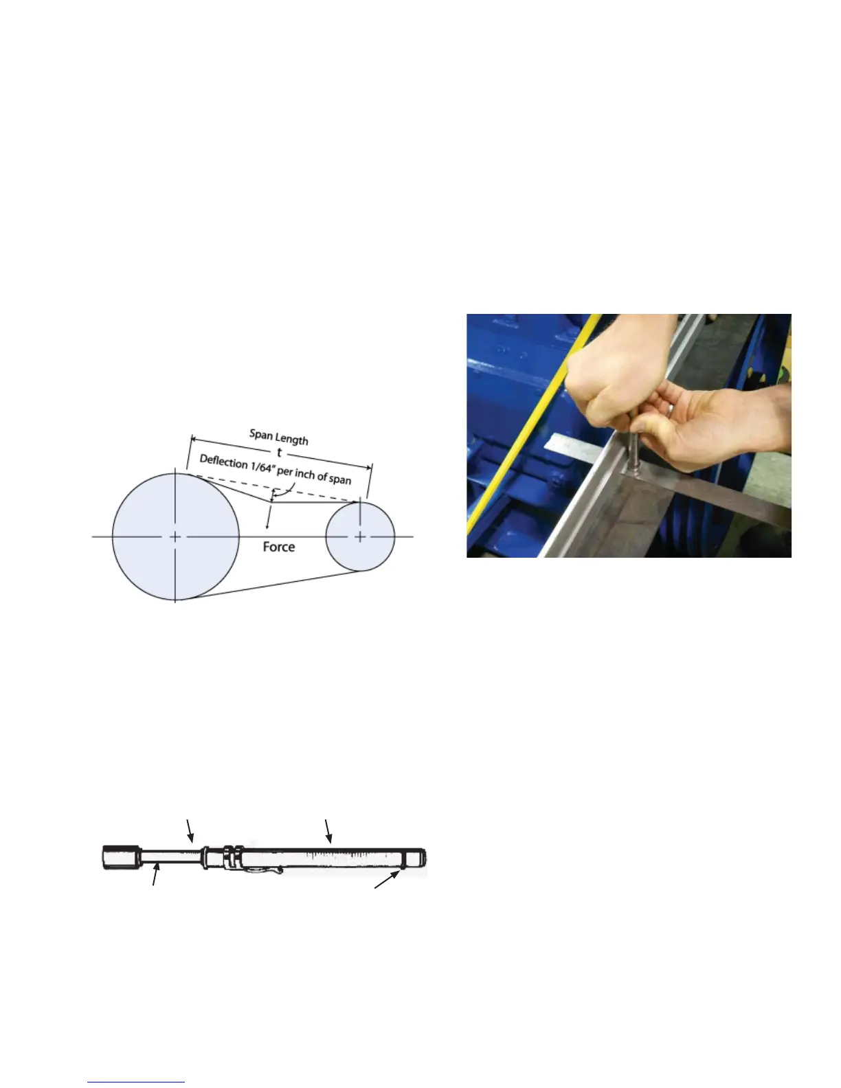
Measure span length (t). See fi gure 19c.
At the center of the span (t), apply force using the
tension tester perpendicular to the span. For banded
belts, place a piece of steel or angle iron across the
band width and defl ect the entire width of the band
evenly.
Use the straight edge placed across the sheave and
fl ywheel above the belt to establish a reference line.
Defl ect the belt until the bottom edge of the lower o-ring
is at the correct defl ection distance. Find the defl ection
force on the upper scale of the tension tester. The
sliding rubber O-ring will move up the scale as the
tester is compressed. See fi gure 19e.
Figure 19c: ‘V’-Belt Defl ection Measurement
Figure 19e: Tension Gauge Example
Compare the defl ection force with the range of forces
recommended (see table 4). If less than minimum the
belt should be tightened. Note: There normally will be
a rapid drop in tension during the run in period and the
belt must be inspected periodically to ensure the belt
tension is within the specifi ed range.
For example if you have a 4B belt with a motor sheave
of 5.4” diameter and a span of 32”, you would defl ect
the belt 32/64” (1/2”) from the reference line. At
that amount of defl ection the force applied should
be 36.4 lbs. max. With new belts, start near the
maximum defl ection force value and check the tension
periodically during the fi rst 24 to 48 hours of service
duty. You must adjust to run in the range of 24.8 lbs.
to 36.4 lbs. See Table 5.
Care should be taken during tension adjustments to
assure that the alignment is maintained.
Upon completion of alignment and tension adjustment,
all mounting hardware should be re-checked for proper
tightness.
Use an appropriate sized V-belt tension gauge, on
the scale reading “Defl ection Inches”, set the O-ring
to show a defl ection of 1/64” per inch of span length
(t). For example a span length of 32” will require a
defl ection of 32/64” or 1/2”.