13
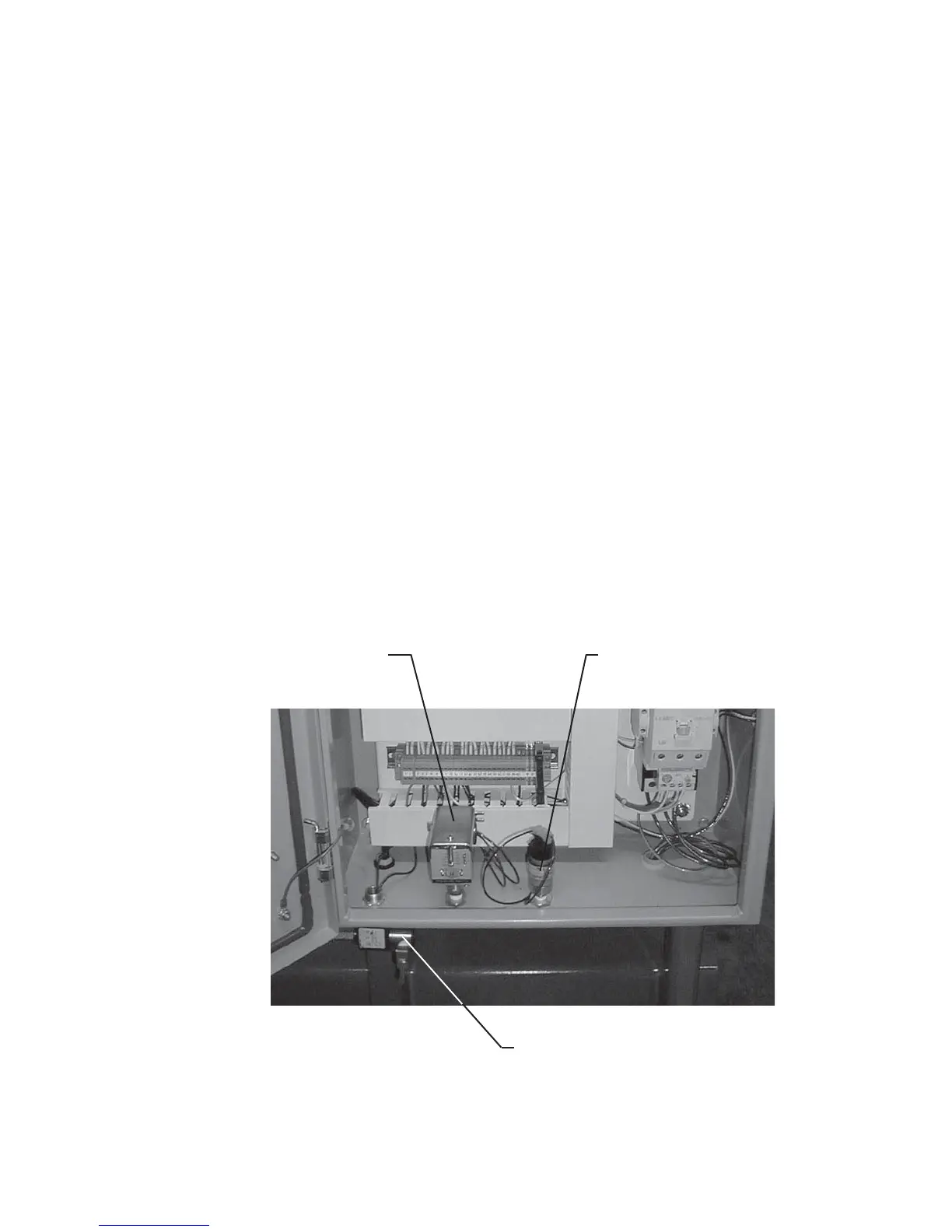
Discharge Pressure Switch with
Adjustable Deadband (connect to
discharge pressure receiver)
Suction Pressure Switch
with Fixed Deadband (connect
to suction pressure receiver)
3-Way Unloader Control Solenoid (connect to
pressure source at least 30 psig above suction
pressure - See Unloading Plumbing Instructions)
in the water temperature through the compressor.
A visual fl ow indicating device is highly recommended
at one or more locations on the coolant inlet and/or
discharge lines. Check discharge coolant piping
backpressure. Excessive backpressure will result in
the compressor overheating. Compressors exposed
to sub-freezing temperatures must be protected from
damage caused by coolant freezing.
Hycomp recommends the use of the following valves
and devices to regulate cooling water:
Solenoid Shutoff Valve – Solenoid actuated valves
control the flow of water through the compressor
system, preventing fl ow at start-up, during shutdown,
or between compressor cycle times.
Thermoregulating Valve – Modulating valves regulate
the fl ow of water to the compressor to maintain a desired
exiting water temperature. They open automatically
when temperature increases at the sensing bulb. No
external power source is required to actuate the valve.
The sensing bulb should be placed in the discharge
water stream, while the main valve body should be
placed in front of the compressor.
Visual Flow Indicator – Flow indicators display to
the operator when there is water fl ow through the
compressor. On large scale water tower systems,
backpressures within the system can prevent water
fl ow through the compressor, causing overheating and/
or freezing problems. A well monitored fl ow indicator
can assure the user that water is fl owing properly
through the system.
COMPRESSOR CONTROL PANEL
Your Hycomp compressor may be provided with a
factory installed compressor control panel (see Figure
6). Optional accessories specific to the control
application requirements may also be included.
A Hycomp compressor control system electrical
schematic is included, if applicable, as well as a basic
piping and instrument diagram (P&ID) for reference
by installation and operations personnel. Instructions
specific to each unique configuration of control
system is provided with the compressor. Components
generally common to many forms of compressor
control schemes require installation as follows:
Control Panel Enclosure – The enclosure must be of
appropriate NEMA rating for the application. Observe
all enclosure warnings when dealing with the enclosure
and its contents. Follow proper UL and NEMA codes
Figure 6: Control Panel Instrument Connection Points