14
when penetrating the enclosure.
Motor Starter – The motor starter must have
appropriate electrical service brought to it by a qualifi ed
electrician. Hycomp control panels list the electrical
service required on a sticker near the starter.
Gas Pressure Switches or Transducers – Generally
located in the control panel, these are used to provide
control feedback to maintain pressure setpoints. Gas
pressure sensing lines of appropriate pressure rating
must be plumbed to the switch or transducer from an
appropriate point of origin. Use minimum 3/8” tubing.
The switches/transducers must be plumbed to a NON-
PULSING source to prevent false readings. Ideally, the
point of origin will be the inlet and discharge receivers.
It is NOT ACCEPTABLE to plumb these switches to
the compressor inlet and discharge piping, as the gas
in this piping pulses.
Unloader Device – The Hycomp control system
generally includes an unloader device to allow loading
and unloading of the compressor system. See the next
section for unloader methods and proper installation
of the device.
UNLOADER CONTROLS
Hycomp compressors are often supplied with an
unloading device of some type. This unloading device
allows the compressor to load and unload based upon
discharge and suction pressures, as well as allowing
the compressor to start and stop unloaded. Even if the
unit does not include a control system from the factory,
many Hycomp compressors have unloader devices
installed. A piping and instrument diagram (P&ID) is
generally including with every Hycomp compressor
system, showing unloader installation
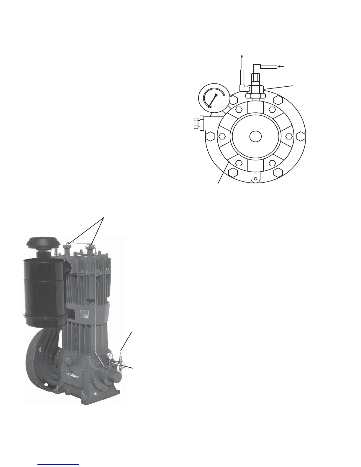
SUCTION VALVE UNLOADING
Suction valve unloaders utilize unloading towers
attached to the compressor cylinder head, and a
three way valve to supply air pressure to the unloader
towers to actuate them. The tower forces the suction
valve open, allowing the compressor to unload. The
three-way valve supplies gas pressure to the unloader
towers, or dumps that pressure out of the unloader
towers (See Figure 7).
Unloader Tower – Provided on all pressure lubricated
Hycomp model ambient air compressors and provided
on some air booster and gas compressors. If the
Unloader
Towers
Constant Speed
Unloader (Pilot
Valve)
Hydraulic
Unloader
Valve
Oil Pump
Figure 8: Hydraulic Unloader Plumbing
To air source
To Unloader Towers or
3-way Check Valve
Hydraulic
Unloader
Valve
Figure 7: Unloader Device Locations