Ref: REFLEX/SCANFLEX MANUAL
EDITION 1: JULY ’97 8
Electrical Connections - MultiPoint System
Controller - Electrical Connections
The Reflex Controller is common to all systems. It has two-part screw terminals. It can be
powered from either an AC or DC supply, but the Multiplexor, Analogue and Relay Modules
must be powered from 110/230V AC.
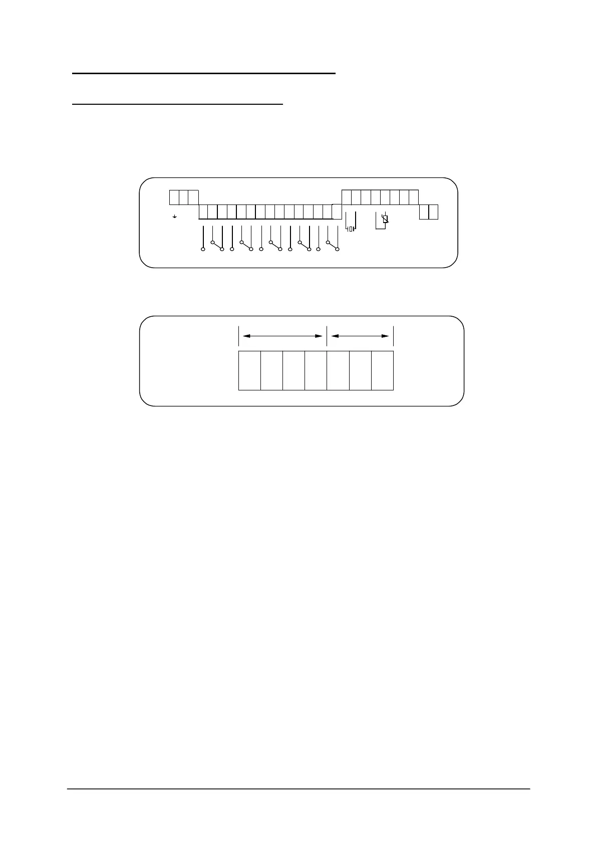
Fig 3. Terminal Layout - Bottom PCB
Fig 4. Communications terminals on top PCB.
AC power supply - connected:- Earth to terminal 1
Neutral to terminal 2
Live to terminal 3
The instrument will automatically accept either 110V or 230V AC ±10%, 50Hz or 60Hz,
12VA. A time lag fuse T160mA is fitted.
DC power supply - connected :- Positive +ve to terminal 27
Negative -ve to terminal 28
The instrument will accept 24V DC + 25%, - 10%. 9W.
A time lag fuse T315mA is fitted.
5 SPDT Relays - rated 8A/250V AC/30V DC resistive, with gold plated contacts for lower
power switching, are connected to terminals 4 to 18, for controlling external group alarms for
pre-determined conditions as detailed on Page 4.
Co-axial Cable Connection to Multiplexor SM-10 - is connected:-
Core to terminal 20
Screen to terminal 19
This cable should be separated from power cables and preferably installed in its own earthed
steel conduit.
1 2 3
E N L
L2 L1
AC POWER
110/230 VAC
+10%/-10%
50/60 HZ 12VA
19 20 21 22 23 24 25 26
27 28
+ -
DC POWER
21.6-30VDC
9W
ISOLATED
ANALOG
OUTPUT
SHIELD
HOT.BLUE
BLACK
+
-
TEMP
SENSOR
TRANS-
DUCER
SHIELD
4 5 6 7 8 9 10 11 12 13 14 15 16 17 18
RELAY 1
RELAY 3
RELAY 4 RELAY 5
RELAY 2
RS232 RS485
Tx GND SCR SCR
-
+
TB5
Rx
31 32 33 34 35 36 37