Ref: REFLEX/SCANFLEX MANUAL
EDITION 1: JULY ’97 2
INSTALLATION
REFLEX - AS A SINGLE POINT INSTRUMENT
Transceiver Mounting
Undo the 6 quarter turn screws on the front panel and open the hinged door to expose the
mounting holes.
Mount the unit on a flat surface and secure it via the 4 mounting holes moulded in the
enclosure. DO NOT use excessive force when tightening the fixings and avoid any distortion
of the enclosure.
Ensure that the mounting surface is not subject to vibration and is not in close proximity to
high voltage cables, contactors or drive controls. The unit should not be mounted in a confined
space where temperatures may exceed the normal working temperature. If the unit is mounted
outside it must be protected from direct sunlight or severe weather conditions.
Remove the required number of hexagon blanking plugs from the bottom of the enclosure and
replace them with appropriate conduit hubs or cable glands to maintain the I.P. rating.
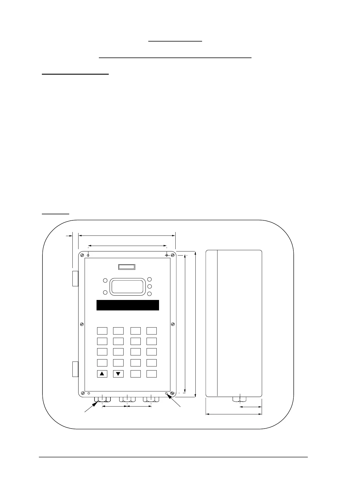
Figure 1:
HYCONTROL
RELAY 1
RELAY 3
RELAY 4
RELAY 5
RELAY 2
REFLEX
2 3 4
6 7 8
0
ENT
MODE
TEST #
5
9
1
CE
DSP
PROGRAMMABLE LEVEL CONTROLLER
40
40
90
40
10
160
130 CTRS
228 CTRS
240
4 MOUNTING HOLES
4.3 DIA (UNDER LID)
3 HOLES
20 DIA PLUGGED
HYCONTROL
.
-