Do you have a question about the Hycontrol REFLEX and is the answer not in the manual?
Details mounting the Reflex unit as a single point instrument.
Describes electrical connections for single point applications.
Details using the Reflex as a multipoint instrument.
Explains system configuration for multipoint setups.
General guidelines for Scanflex system configuration.
Describes the minimum system configuration for Scanflex.
Details a Scanflex system with an Analogue Output Module.
Describes Scanflex system with SR-10 Relay Module.
Details Scanflex system with Analogue and Relay Outputs.
Mounting instructions for the Reflex/Scanflex Controller.
Mounting instructions for Multiplexor, Analogue, and Relay modules.
Specific mounting for the Multiplexor module.
Specific mounting for the Analogue Module.
Specific mounting for the Relay Module.
Electrical connections for the Reflex Controller in multipoint systems.
Details analogue output connections.
Describes connections for temperature compensation sensors.
Explains RS485 communication between modules.
Details RS232 communication to external devices.
Electrical connections for the Multiplexor SM-10.
How to connect transducers to the Multiplexor.
Electrical connections for the Analogue Module SA-10.
Electrical connections for the Relay Module SR-10.
Instructions for identifying and addressing system modules.
Installation points to avoid for transducers.
Guidelines for installing transducers in standpipes.
Instructions for mounting transducers.
Information regarding temperature sensor installation and use.
A checklist to perform before switching on the system.
Describes the normal 'RUN' mode display.
Explains how to display secondary functions.
How to check the status of Scanflex modules.
Explains the basic principles of system programming.
Details the security code system for programming access.
Steps to enter programme mode and view data.
How to navigate and select different parameters.
Process for changing parameter values.
How to change the selected point number in multipoint mode.
Steps to exit programming and return to run mode.
Procedure to reset the system to factory default settings.
Explains the primary functions of the keypad keys.
Describes secondary functions of the keypad keys.
Details the sequence of parameters for programming.
Parameters related to basic system setup.
Parameters for configuring relays.
Parameters for failsafe functions.
Parameters for analogue output configuration.
Parameters for temperature compensation.
Parameters for vessel volume conversion.
Parameters for scanner control.
Parameters for serial communications.
Parameters for echo detection.
Miscellaneous operational parameters.
Parameters for system testing.
Parameters for storing serial numbers and codes.
Parameters for system resets.
Definitions for basic setup parameters (Pr.1-Pr.7).
Defines the type of transducer used for each point.
Sets application type and measurement units.
Defines the distance to the furthest point away.
Defines the measurement span between nearest and furthest points.
Defines a zone near the transducer to ignore echoes.
Sets the maximum rate of level change.
Describes controller relay functions in multipoint systems.
Explains point-specific relays in multipoint systems.
Defines relay designations and settings.
Sets the designation for Relay 1.
Sets the designation for Relay 2.
Sets the designation for Relay 3.
Sets the designation for Relay 4.
Sets the designation for Relay 5.
Defines the failsafe state for Relay 1.
Defines failsafe for analogue output and display.
Sets the time delay before failsafe activation.
Configures the analogue output type.
Sets an offset for the analogue output.
Defines the span for the analogue output.
Tests the analogue output functionality.
Enables or disables the temperature sensor.
Sets compensating temperature if sensor is not fitted.
Tests the temperature sensor.
Defines the vessel shape for volume conversion.
Input for vessel dimension H.
Input for vessel dimension L.
Configures display conversion for volume.
Enables vessel linearisation for non-standard shapes.
Resets point-specific parameter data to factory defaults.
Allows copying point data to other points.
Defines the total number of system modules.
Sets max time spent on a single point.
Enables manual scanning for commissioning and fault finding.
Enables serial communication via RS232.
Assigns a unique station number for polled data transfer.
Sets the maximum allowable gain.
Restricts the gain level.
Selects the echo extraction technique.
Defines the velocity of sound in the medium.
Configures continuous display of selected parameters.
Corrects minor reading errors or prevents loss-of-echo.
Sets the number of decimal places for display.
Displays the current software revision.
Counts system power downs or resets.
Defines the status of relays during programming.
Tests the relays in the controller.
Tests the transmitter function.
Simulates instrument operation for testing.
Non-adjustable filter setting.
Non-adjustable filter setting.
Displays the unit's serial number.
Allows entry and storage of a new security code.
Resets relay hours and start totalisers.
Resets the system to factory default settings.
Details a single point level measurement application.
Application with volume conversion and temp. probe.
A multipoint scanner application example.
Troubleshooting guide for single point Reflex systems.
Troubleshooting guide for multipoint Scanflex systems.
Troubleshooting blank displays and blown fuses.
Troubleshooting power-up, keypad, and analogue output problems.
Troubleshooting 'Loss of Echo' and display value errors.
Troubleshooting analogue output and display value problems.
Troubleshooting display values and temperature compensation.
Troubleshooting relay operation and PCB humming.
Troubleshooting common faults within the multipoint controller.
Troubleshooting specific faults for Multiplexor, Relay, Analogue modules.
Troubleshooting Multiplexor power and communication LEDs.
Troubleshooting Relay module power, comms, and switching.
Troubleshooting Analogue module power, comms, and output.
Troubleshooting various analogue module output problems.
Troubleshooting operational faults related to display values.
Troubleshooting operational faults causing display inaccuracy.
Troubleshooting temperature indication and reading errors.
Specification details for different transducer models.
Installation points to avoid for transducers.
Guidelines for installing transducers in standpipes.
Instructions for mounting transducers.
Dimensional drawings for RXV15 and RXT15 series.
Wiring diagrams for standard and temp. compensated transducers.
Dimensional drawing for RXM19 transducer.
Dimensional drawing for RXM19ER transducer.
Dimensional drawing for Rotational Aiming Kit.
Dimensional drawing for Rotational Aiming Kit (RAK-ER).
Lists the available temperature sensors.
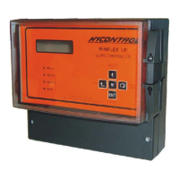
Detailed description of the Reflex/Scanflex Controller.
Technical specifications for the Reflex Controller.
Detailed description of the Multiplexor SM-10.
Technical specifications for the Multiplexor SM-10.
Detailed description of the Relay Module SR-10.
Technical specifications for the Relay Module SR-10.
Detailed description of the Analogue Module SA-10.
Technical specifications for the Analogue Module SA-10.
Feature for volume conversion on irregular shaped vessels.
Steps for mapping vessel linearisation profile.
Keyboard controls for entering linearisation data.
Guide to inputting level and volume data for linearisation.
Notes on keypad time-outs and data entry.
Example of mapping vessel data for linearisation.
Table of required values for vessel mapping.
Notes on data entry for unused points and values.
Table of parameter settings for Scanflex systems.
| Technology | Ultrasonic |
|---|---|
| Protection Rating | IP65 |
| Output | 4-20mA, relay |
| Power supply | 24 VDC |
| Mounting | Wall or panel |
| Accuracy | ±0.25% of full scale |
| Operating Temperature | -20°C to +60°C |