Appendix 2
Ref: REFLEX/SCANFLEX MANUAL
EDITION 1: JULY ’97 56
REFLEX/SCANFLEX MODULE DESCRIPTION AND SPECIFICATIONS
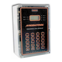
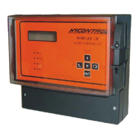
REFLEX/SCANFLEX CONTROLLER
DESCRIPTION
The Reflex/Scanflex Controller is a stand-alone single point level instrument or can form the
heart of a scanner system. It configures the system, takes all the measurement and controls the
setting of all outputs.
It consists of a single main board fitted with an intelligent display board in a standard
Polycarbonate enclosure. All data to configure and test the Controller and the system is input via
the membrane keypad.
The display board has its own microprocessor which allows it to generate various displays on the
graphics LCD module without slowing down the main processor.
The Controller is fitted with relays which can be individually programmed in the Reflex mode
but are used to provide group status alarm in the Scanflex mode. Their alarm state is shown by
red LED's on the display.
The analogue output on the Controller gives an output that corresponds to the latest value sent to
the analogue module. In Scanflex mode it therefore gives an output which changes as the
Controller scans around the measurement points.
The Controller is fitted with two serial communications ports. The RS232 is available to the
customer for connection to a local computer to obtain data on the displayed value, temperature
and alarms for each point on the system. To use this the customer will need to request the
Communications Polled Data Transfer Leaflet.
The RS485 port is also available to transmit data to the customers computer in Reflex mode, but
is used to communicate with the Multiplexor, Relay and Analogue Modules in the Scanflex
mode.
The module is fitted with two part screw terminal connectors.