Ref: REFLEX/SCANFLEX MANUAL
EDITION 1: JULY ’97 4
INSTALLATION
REFLEX - AS A MULTIPOINT INSTRUMENT
System Configuration
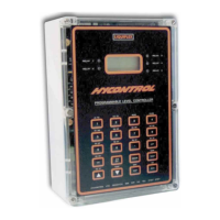
The REFLEX controller can be used as the heart of a SCANFLEX System which will monitor
and control the level in 2 to 10 separate vessels. The transducer for each vessel is connected to
the controller via a 10 point Multiplexor SM-10. A full description of the Multiplexor and
PCB layout is shown on Page 58 to 61.
The Controller will output an analogue signal proportional to level or distance for each point as
it is scanned, but if a continuous mA signal is required for each point then an Analogue Output
Module SA-10, must be connected. A full description of the Analogue Output Card and PCB
layout is shown on Page 65 to 67
When used in the multipoint Scanflex mode the 5 relays in the Controller are pre-assigned as
Group Alarms and show the following:-
Relay 1 Indicates that Relay 1, on one of the points being monitored, has operated.
Relay 2 Indicates that Relay 2, on one of the points being monitored, has operated.
Relay 3 Indicates a loss of echo on one of the transducers.
Relay 4 Indicates that there is a fault in the communications with a module.
Relay 5 Indicates that the instrument is in Programme Mode.
To provide two separate alarm or control relays for each point a Relay Module SR-10 must be
connected.
A second Relay Module can be added, to provide 2 more alarms or relays for each point. A full
description of the Relay Module and PCB layout is shown on Pages 62 to 64.
Scanflex Configuration General
The modular approach to the design of the SCANFLEX system allows a choice of different
system configurations to be built. The individual modules required to build each system can be
mounted remote from each other. The controller is linked to the Multiplexor with RG62AU
cable and communication between the Controller and all modules is via a single RS485 cable.
Suitable cables include Belden 8451, Alpha 2461 or equivalents.
A little care in the selection of the location for the individual modules can considerably reduce
the cost of cabling.
i.e. The Multiplexor Module should be close to the transducer.
The Analogue Module should be close to where the outputs are required.
The Relay Module should be close to the alarms or controls it operates.
The maximum distance between the Controller, through the Multiplexor, to each individual
transducer, should not exceed 300m.
The Relay and Analogue Modules can be up to 2000m from the Controller, or greater if
repeater modules are used on the RS485 communications.

 Loading...