Appendix 2
Ref: REFLEX/SCANFLEX MANUAL
EDITION 1: JULY ’97 65
SCANFLEX ANALOGUE MODULE SA-10
DESCRIPTION
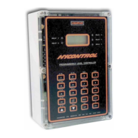
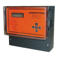
The Scanflex Analogue Module is mounted in an IP65 polycarbonate enclosure with a clear lid.
(See Page 59)
The Module controls the setting of an analogue output for each point of measurement. The
current output has 12-bit resolution and gives 4-20mA into 750 ohms.
The module is fitted with an RS485 serial port for communications with the controller. When a
valid message is received, the green 'comms' l.e.d. will flash. The link (LK1) by TB1 connects a
line termination resistor into the communications circuitry. It is used only when the Module is
that last one on the system configuration
The selector switch (SW1) marked 'UNIT' is used to select the number that uniquely identifies the
module to the controller. For the analogue module settings 2-15 can be used. Each Module on
the system must have a different setting number. if the switch is set to zero the module can be
tested using the momentary switches SW2 and SW3. By pressing 'TEST 1' (SW2) all of the
analogue channels will be set to a value of approximately 20mA. To exist from the test condition
move the selector switch (SW1) away from zero to its correct position.
When the Module is initialised, the analogue outputs will be at a value of 2.8mA to signify no
valid reading, until data is transmitted for that point.
The Module is fitted with two part screw terminal connectors for ease of wiring, with separate
connectors for each point. A full description of the connection is shown on Page 66.