Pg 3.2 H22
BLADE BRUSH ADJUSTMENT
The blade brush is properly set when machine leaves the factory, but it
wears out during operation and needs to be readjusted periodically. The
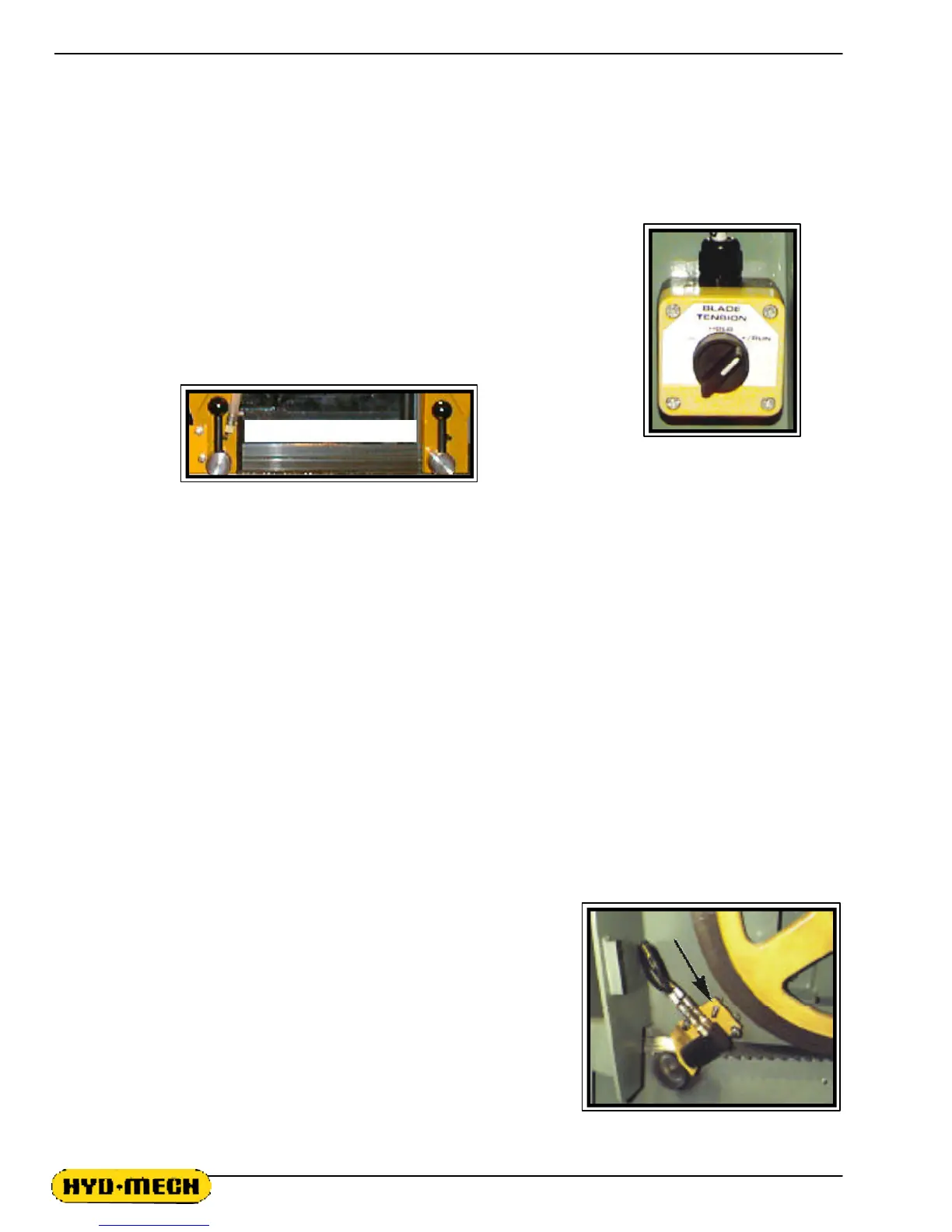
blade brush assembly is found behind the drive side door and is shown in
the photo.
To adjust the assembly, loosen the hex nut, turn the set screw
counterclockwise until the wires on the brush touch the bottom of the
blade gullets and tighten the hex nut.
The brush should be replaced as it becomes worn to approximately 70%
of it's original 3" diameter. Replacements can be purchased through your
Hyd-Mech Dealer.
BLADE CHANGING PROCEDURE
NOTE: Wear gloves, safety glasses and a long sleeve shirt for protection from the sharp blade. The
hydraulics should be OFF any time the operator has his/her hands in contact with the blade.
1. Select MANUAL mode and raise the head so the drive door will clear the electrical control panel.
2. Release the blade tension by turning the Blade Tension Switch to "-".
3. Remove the blade guard.
4. Shut the machine off and open the idler and drive doors.
5. Loosen the carbide locking levers by turning counter clockwise 1/4 turn.
6. At the top of the head, the saw blade runs in a protective channel. Grip the blade at each end of this
channel and twist the blade teeth down past the channel and slide the blade forward. Let the blade rest on the
out feed table, then slide the blade down and out of the carbide guides.
7. Before installing the new blade, check that it measures 1.615" wide including the teeth. Some blade
manufacturers supply blades that measure 1.5" including the teeth. The same applies to 2" blades, they should
measure 2.120". In this case you may not be able to adjust the head down limit to complete the cut.
8. Your new blade will be in a coil. While wearing gloves, hold the blade away from yourself, twist the blade to
uncoil it. Do not let the blade teeth bounce on the concrete floor as some damage to the blade may be caused.
9. Place the new blade in the carbide guides and then slide the blade over the wheels. The teeth should be
pointing towards the drive side as they pass through the carbide guides.
10. Turn the machine on and the blade tension switch to the "+ RUN" position, turn the two carbide locking
handles clockwise to the locked position. Jog the blade a few rotations to check that the blade is not moving
on or off the wheels.
(5) Carbide levers in locked position
(2) Blade tensioning switch in
the tension or run position.
Blade brush and adjusting nut &
screw.



 To Next Page