1918
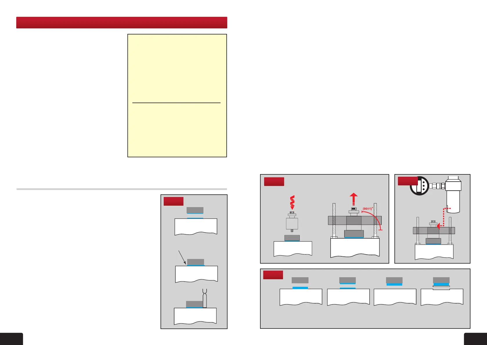
Fig 27
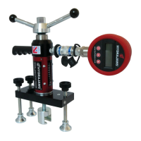
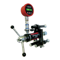
6. MATERIAL BOND TESTER KIT
Procedure for preparing samples for pull-off testing:
1. Clean the steel dollies (degrease and grit blast unless
otherwise stated). This will help to prevent interfacial
failures at the dolly interface.
2. For concrete substrates drill through the repair system
with diamond core drill at (90±)º to the surface into the
test surface by ~5mm or more.
This ensures a consistent bond area and will therefore
help reduce variations in the test results.
3. Clean the substrate test surface as recommended by
the manufacturer.
4. Mix the adhesive as recommended by the adhesive
supplier and add 1% by weight of ballotini (usually
0.5mm unless stated otherwise).
Adding ballotini will reduce alignment errors and
therefore help reduce variations in the test results.
5. Apply adhesive to steel dolly.
• M2000 Medium Duty Tester with
Digital/Analogue gauge to 25kN
• Bond test stool with adjustable legs
• 10x50mm & 10x 75mm steel bond
discs
• Bond test plug
• Calibration Certicate
• Padded Carrying Case
(Can accommodate 20x50 & 20x75 discs)
ON SITE PULL
-
OFF METHOD
Equipment that may be required in
addition to the standard kit contents:
• Adhesive • Spatula
• Bondline spacers -
i.e.ballotini (glass spheres)
• Diamond-coated core drill
The bonding strengths of a wide and
varied range of materials including
concrete, screeds, repair mortars, epoxy
resin coatings, laminates, plastics,
paints and enamels may be accurately
determined using the Hydrajaws Material
Bond Tester.
Adequate direct tensile strength or
bonding strength between two layers is
important if repairs to concrete structures
or additional overlays and screeding on
existing concrete is to be structurally
sound.
The pull-off test as a means of projecting
the compressive strength of concrete
and other materials involves bonding
a circular steel disc to the surface by
means of an epoxy resin adhesive.
KIT CONTENTS:
A controlled tensile force is then applied to the disc, and as the strength of the bond is
greater than that of the material under stress it will eventually fail in tension. From the
area of the disc and the force applied at failure it is possible to calculate a nominal tensile
strength for the material.
DOLLY
TEST SURFACE
DOLLY
TEST SURFACE
DOLLY
TEST SURFACE
DOLLY
TEST SURFACE
DOLLY
TEST SURFACE
DOLLY DOLLY
TEST SURFACE
Excess adhesive
extruded
TEST SURFACE
DOLLY
TEST SURFACE
LOAD
Loading
bolt
DOLLY
TEST SURFACE
DOLLY
TEST SURFACE
DOLLY
TEST SURFACE
DOLLY
TEST SURFACE
DOLLY
TEST SURFACE
DOLLY
DOLLY
TEST SURFACE
Excess adhesive
extruded
TEST SURFACE
DOLLY
TEST SURFACE
LOAD
Loading
bolt
DOLLY
TEST SURFACE
DOLLY
TEST SURFACE
DOLLY
TEST SURFACE
DOLLY
TEST SURFACE
DOLLY
TEST SURFACE
DOLLY DOLLY
TEST SURFACE
Excess adhesive
extruded
TEST SURFACE
DOLLY
TEST SURFACE
LOAD
Loading
bolt
a
b
c
Fig 26
DOLLY
TEST SURFACE
DOLLY
TEST SURFACE
DOLLY
TEST SURFACE
DOLLY
TEST SURFACE
DOLLY DOLLY
TEST SURFACE
Excess adhesive
extruded
TEST SURFACE
DOLLY
TEST SURFACE
LOAD
Loading
bolt
Fig 29
Interfacial failure
to dolly.
Cohesive failure of
the adhesive.
Interfacial failure
to substrate.
Substrate failure.
6. Apply adhesive to substrate test surface (g 26a). This ensures the adhesive wets out
both surfaces and helps prevent interfacial failures.
7. Press the steel dolly into the substrate test surface with a rm pressure (g 26b)
DO NOT ‘seat’ the dolly by twisting it into position. If the dolly is twisted into position it
will increase the likelihood of interfacial failures.
8. Remove excess adhesive from around the edge of the dolly without disturbing its
position (g 26c). This ensures a consistent bond area and will therefore help reduce
variations in the test results. If working on a vertical or overhead surface, ensure the
dollies are held rmly in position until the adhesive has cured.
9. Connect centering plug to disc using the 8mm thread and hand tighten until bottom is
ush with top disc (g 27a).
10. Lower load stool centre hole over centering plug and adjust the 3 screws until top of
plug is ush and level with top of stool. It is essential that this levelling is carried out
carefully to ensure a square and smooth pull through the stool. The load applied to the
centre of the dolly should be at an angle of 90º±1 (g 27b).
11. Slide Tester over adaptor on top of plug and t 22mm socket and ratchet to the
operating nut (g 28). Secure equipment so that it does not move during testing.
This will cause excess misalignment which will reduce pull-off strengths.
12. Operate ratchet in a clockwise direction until required loading is obtained or bonding
breaks. Record test temperature, failure load and failure mode (g 29) (Record mixed
failure modes in percentages of bond area, i.e. 90% substrate failure, 10% cohesive
failure). Maximum loading achieved will be shown by red indicator pointer. Use this
reading to calculate the bond strength Mpa from the chart on page 20.
a
b
TEST SURFACE
DOLLY
TEST SURFACE
LOAD
Loading
bolt
TEST SURFACE
DOLLY
TEST SURFACE
DOLLY
DOLLY
TEST SURFACE
DOLLY
TEST SURFACE
LOAD
Loading
bolt
TEST SURFACE
DOLLY
TEST SURFACE
DOLLY
TEST SURFACE
LOAD
Loading
bolt
TEST SURFACE
DOLLY
TEST SURFACE
DOLLY
Fig 28
 Loading...