98
Remove the insulation around the fastener.
Mount the locking adaptor into the tester (see
Section 1 General testing procedure). Thread
the insulation adaptor into the locking adaptor
fully then back off until horizontal.
By holding the tester, slide the head of the
insulation fastener (a) between the two plates
with the stem of the xing resting in the slot in
the lower plate (b) and adjust the legs on the
load spreading bridge to suit the base material.
Ensure that the pull-out force acts along the
axis of the xing being tested (g 15).
2.3 THE INSULATION ADAPTOR
2.2 M10, M12, M16 AND M20 THREADED STUD ADAPTORS
Fig 12
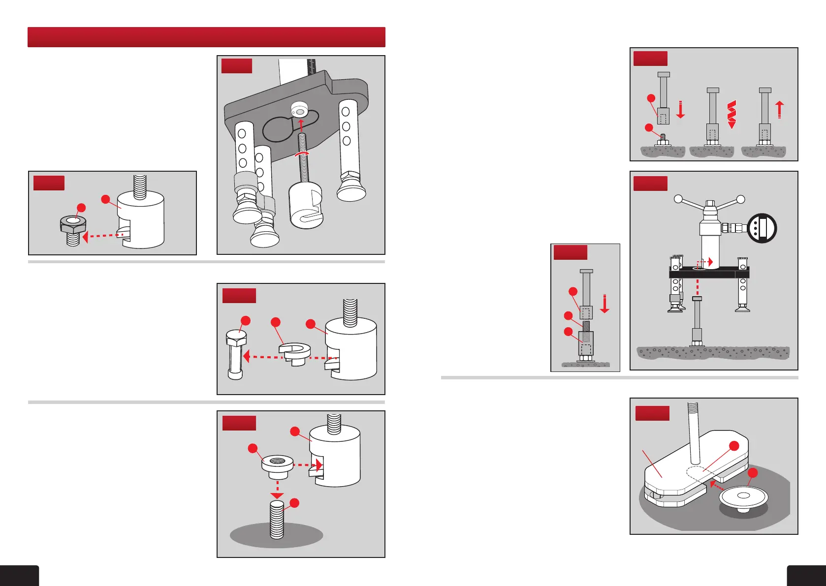
Suitable for testing sleeve and stud anchors.
(g 12) After the anchor has been set
in accordance with the manufacturers
recommendations, a suitable threaded
rod (a) is screwed into the anchor and the
adaptor (b) then tted. The length of the
threaded rod to be screwed into the anchor
must be at least equal to the diameter of the
anchor.
Remove the locking adaptor if tted (see
Section 1 General testing procedure).When
the adaptor is securely tted to the anchor
thread position, place the tester over the
adaptor, passing the head through the hole
in the bridge and engage it in the pulling
jaw of the tester (g 13). Level the load
spreading bridge with the adjustable legs
before commencing the application of
the load.
Fig 13
b
a
1 2 3
Fig 15
a
b
Note: (g 14) To use
the optional M30 HD
Threaded stud adaptor,
rst attach 45mm M20
thread piece (c) into
adaptor (e) and attach to
the xing. Then thread
the M20 Adaptor (d) and
proceed as above.
d
c
e
Fig 14
2. PULLING ADAPTORS
2.1 THE BOLT TEST ADAPTOR
Using the bolt test adaptor directly
Using the bolt test adaptor with the slotted button adaptor
Using the bolt test adaptor with
the threaded button adaptor
For M16 nuts, (g 8) the bolt tester
adaptor (a) directly engages the nut (b) in
the pulling jaw.
Mount the locking adaptor into the tester
(see Section 1 General testing procedure).
Then thread the bolt tester adaptor into the
tester body (g 9).
Fig 8
For testing xings where a connection is
made underneath the head of the xing or
anchor the slotted button adaptor is used.
Mount the locking adaptor into the tester
(see Section 1 General testing procedure).
Then thread the bolt tester adaptor into the
tester body (g 9).
The slotted button adaptor (a) slots into
the bolt tester adaptor (b) and engages the
xing (c) (g 10).
For testing threaded xings the threaded
button adaptor is used.
Mount the locking adaptor into the tester
(see Section 1 General testing procedure).
Then thread the bolt tester adaptor into the
tester body (g 9).
The threaded button adaptor (a) threads
on to the xing (c) and then slots into the
bolt tester adaptor (b) (g 11). Ensure the
button adaptor has at least 2 complete
thread turns on the xing and is secure.
Fig 10
Fig 11
Fig 9
b
c
a
b
c
a
Insulation
Adaptor