2120
7. OPTIONAL LOAD SPREADING BRIDGES
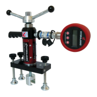
8. LEG ADJUSTMENT
ACTUAL PULL FORCE READ DIRECT FROM GAUGE
50mm dia Disc Area 1964mm
2
Actual Pull Force 75mm dia Disc Area 4418mm
2
Bond Strength kN Bond Strength
MPA Mpa
0.51 1.00 0.23
1.01 2.00 0.45
1.53 3.00 0.68
2.03 4.00 0.90
2.55 5.00 1.13
3.05 6.00 1.36
3.56 7.00 1.59
4.07 8.00 1.81
4.58 9.00 2.04
5.09 10.00 2.26
5.06 11.00 2.49
6.11 12.00 2.72
6.62 13.00 2.94
7.13 14.00 3.16
7.63 15.00 3.40
8.15 16.00 3.62
8.66 17.00 3.85
9.16 18.00 4.07
9.67 19.00 4.30
10.20 20.00 4.52
10.70 21.00 4.98
11.71 23.00 5.20
12.22 24.00 5.43
12.73 25.00 5.65
Mpa (Mega Pascales) = N/mm squared
Mpa = Actual Pull Force divided by Area of Disc x 1000
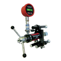
MATERIAL BOND TESTER KIT continued..
IMPORTANT! A low reading will be obtained if:
• The pull-off tester is misaligned and not perpendicular to the specimen
• The specimen is misaligned and not perpendicular to the pull-off tester
• The bondline is not of uniform thickness (0.5mm)
• A sudden or erratic loading is applied.
Note: This information is for guidance only. Please also refer to adhesive manufacturer’s
data and safety sheets.
Replacement discs available in both sizes from stock.
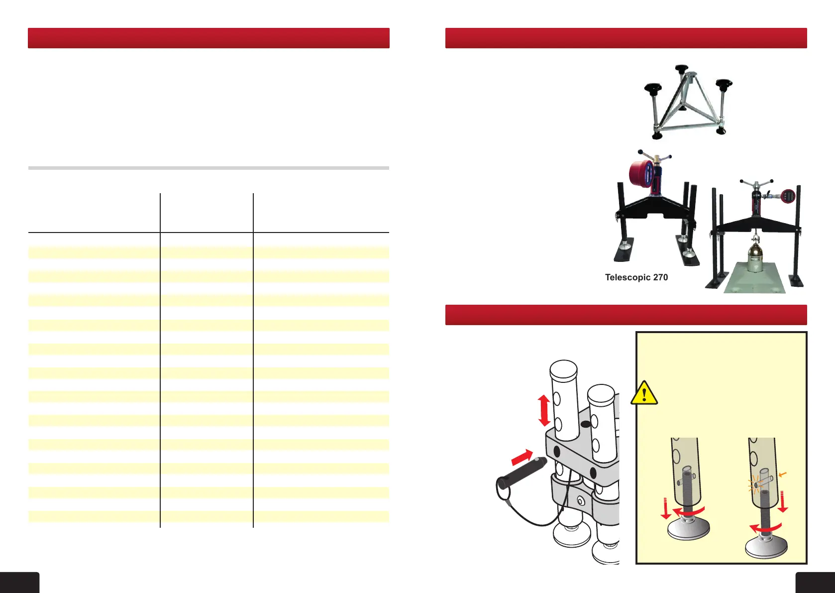
Pyramid Stool
Telescopic 270
Telescopic
600
Hydrajaws offer three optional load
spreading bridges, a pyramid stool with
threaded legs and a 270mm or 600mm
wider span bridge with telescopic legs.
These are designed to attach easily to
the Hydrajaws M2000 Tester.
To install, rst remove any existing load
spreading bridge by removing the two
positioning screws using the 3mm ball
driver. Use the same screws to secure
the tester to the optional bridge.
The 270mm and 600mm load
spreading bridges can be installed so
the tester is operated in two different
positions as illustrated. The legs are
fully adjustable to suit the testing
application.
A thread adaptor coupler is also
supplied to extend the accessory in
use. The Pyramid stool is supplied
with an extended bolt test adaptor.
To adjust leg height:
- pull out pin.
- adjust leg to desired
height.
- line up hole and
insert pin until it clicks
into place.
Fine adjustment can be made by
unscrewing the feet by no more than
approximately 15mm.
Caution:
If light is visible through the bottom
indicator holes then the leg has
been unscrewed too far. Dont
expose more than 15mm of thread.
8
4