4 5
1. GENERAL TESTING PROCEDURE
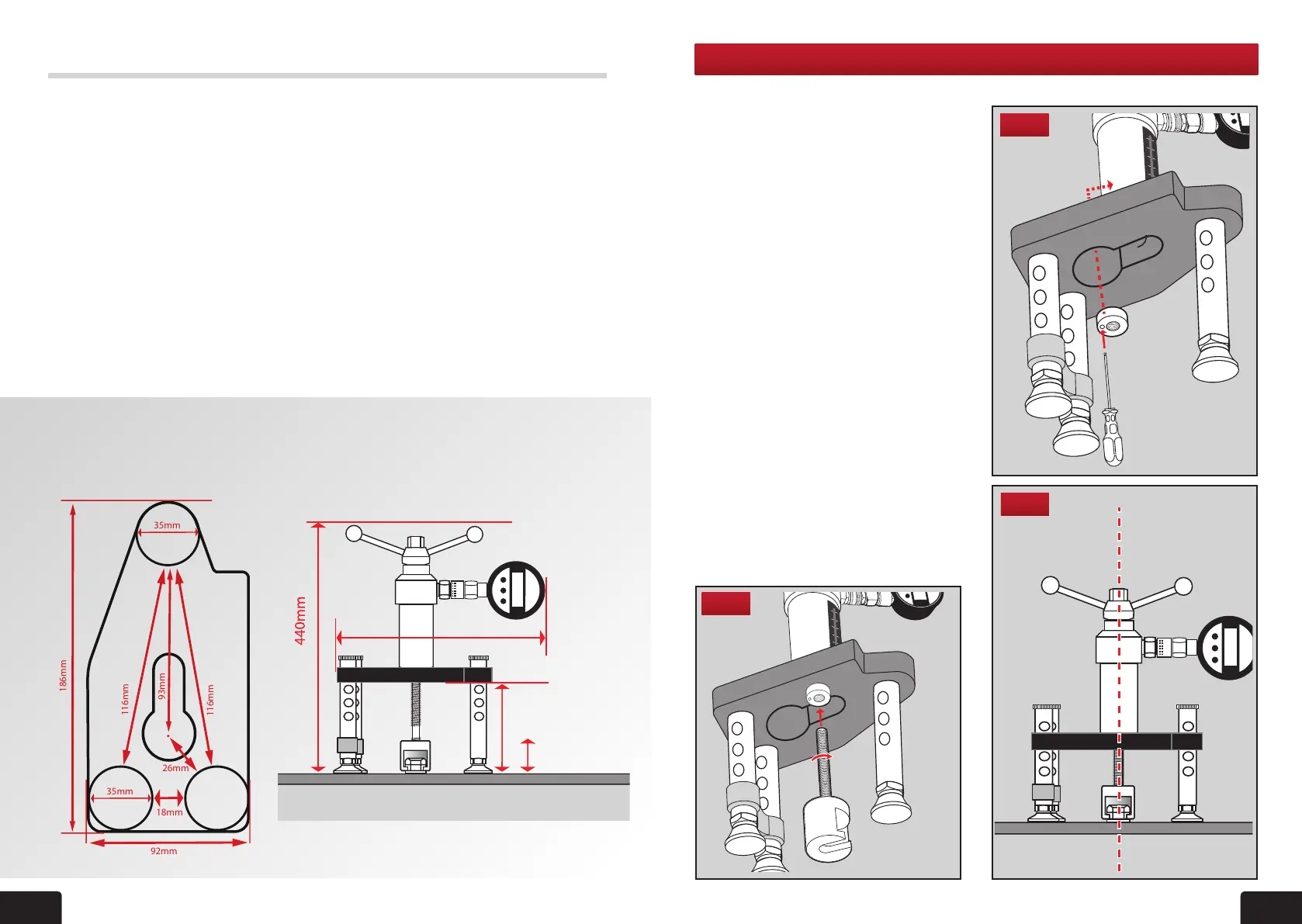
SETTING UP THE TESTER
1 Fit the appropriate adaptor to the tester.
Example shown is a bolt tester adaptor.
(For tting of other adaptors please see
individual instructions in this manual).
2. The tester is supplied with a locking
adaptor tted into the tester body.
This locking adaptor can be removed
for tting of different adaptors by using
the 3mm Ball Driver. When replacing
back in ensure it is fully engaged into
the tester body before tightening
(g 1). Thread the bolt tester adaptor
into this, until it is fully engaged, using
a quarter turn for position (g 2).
3. Make nal adjustments so that the bolt
tester adaptor, tester and xing are
aligned (g 3).
4. Position the tester so that the gauge
can be easily read.
5. Adjust the length of the telescopic legs
(see section 8) so that all three are in
contact with the base material and the
load spreading bridge is aligned and
level by referring to the bubble levels on
the bridge.
Fig 3
Fig 2
Fig 1
• Pull-out load range 0-25kN/lb/f
• Weight
Tester only 2.2kg
Packaged weight 8kg (will vary)
• Stroke scale 0-50mm
• Effective stroke 50mm
• Load gauge Interchangeable
• Casing Aluminium
• Loading jaw Pivotable through
360° with Spring
return
• Operating handle Standard size
with
integrated 22mm
operating nut for
conned spaces
TECH SPECIFICATIONS
Bridge Footprint and Tester dimensions
Load Gauges
• Ranges available: Digital: 0-25kN
• Accuracy: Digital to +/-0.5% fsd
• Indication of pull-out load
• Calibrated in kN
• ALL gauges are dual scale. kN/lbf.
Digital gauges are supplied set to kN
and are easily switchable to lbf by
the user.
• Traceable UKAS calibration certicate
supplied with each gauge
• Protective rubber cover
• Impact resistant glass
• Protection against sudden load relief
(i.e. sudden failure of xing)
• Digital: peak hold memory
• Working Temperature:
Digital: -30°C to +85°C
M2000 Bridge Footprint M2000 Dimensions
4
350mm
182mm
Highest
93mm lowest
116mm
186mm
35mm
35mm
116mm
93mm
92mm
26mm
18mm