Do you have a question about the Hydrotek 2000 and is the answer not in the manual?
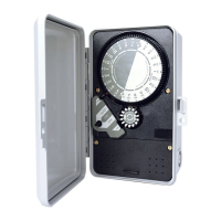
Rotates one clockwise revolution every 24 hours. Controller is programmed for automatic operation with timing pins.
Has 14 pin locations for a 2 week program. Controller operates in AUTO only on days programmed by pin depression.
Indicates controller function: ON for manual, AUTO for automatic, OFF to stop functions.
Secures controller chassis to enclosure.
Allows for input and output electrical connection. Consult diagrams prior to wiring.
Instructions for removing face, making wire connections, and reinstalling controller for 1000 series.
Instructions for removing lower cover, making wire connections, and reinstalling cover for 2000 series.
Presents wiring and circuit diagrams for various 1000 Series models.
Presents wiring and circuit diagrams for various 2000 Series models.
Addresses issues with timekeeping, including power, voltage, and drive gear problems.
Diagnoses causes for the controller remaining ON, such as switch activation, wiring, or adjustment.
Troubleshoots issues preventing the controller from turning ON in manual mode, checking power and wiring.
Addresses failures in automatic operation, including daywheel programming, switch settings, and adjustments.
This document provides installation, troubleshooting, and operational instructions for the Hydrotek® 1000 and 2000 Series single station controllers, as well as the 2510, 2514, and 2520 Rainswitch Ready Controllers. These devices are designed to manage automated systems, primarily for irrigation, by controlling the timing and duration of operations.
The core of the controller's functionality revolves around several key components:
Time Dial: This dial completes one clockwise revolution every 24 hours. It is used to program automatic operations by inserting timing pins into its holes. To set the correct time of day, align the "TIME" arrow with the current time displayed on the dial. It's crucial to set the Time Dial only in the clockwise direction, never forcing it in reverse.
Day Wheel and Retained Pin Assembly: This component features 14 pin locations, allowing for a two-week program. The controller will only operate automatically on days where the corresponding day wheel pin is fully depressed. To set the correct day, align the "DAY" arrow with the day indicated on the wheel. Pins should be pushed down for desired operation days and gently pulled out for days when operation is not desired.
AUTO-OFF-ON Switch Knob: This knob allows users to select the desired function of the controller. Turning it to "ON" enables manual operation, "AUTO" activates automatic operation based on the programmed settings, and "OFF" stops both manual and automatic functions.
Chassis Screws: These screws secure the controller chassis to its enclosure, ensuring the internal components are protected.
Electrical Connection Strip (2000 Series): This strip facilitates the input and output electrical connections for the controller. Users should consult the Electrical Circuit and Connection Diagrams before proceeding with wiring.
To ensure proper functioning, follow these steps for setting up the controller:
Setting Day of Week and Time of Day: First, rotate the Day Wheel until the correct day aligns with the "DAY" arrow. Next, turn the Time Dial CLOCKWISE until the current time aligns with the "TIME" arrow. Remember, the Time Dial must only be turned clockwise.
Manual Operation: To operate the system manually, turn the Auto-Off-On switch to "ON." Once manual operation is no longer required, return the switch to "OFF."
Daily Operation: The Day Wheel offers 14 days for programming. For each day you wish the controller to operate, fully depress the corresponding day wheel pin. For days when operation is not desired, gently pull the pins out.
Setting Operating Times: The 24-hour Time Dial is divided into ninety-six 15-minute increments. Timing pins should be inserted into the Time Dial to specify the desired operating times. Each controller includes a package of white 15-minute pins. Longer operating periods can be achieved by placing multiple white pins consecutively. Shorter duration pins, such as yellow 7-minute pins and orange 4-minute pins, are also available.
Operating a Multiple Zone Valve: For systems with multiple zone valves, operating times for each zone are represented by one or a group of pins on the Time Dial. Ensure there is at least one pin omitted between each zone's set of pins on the Time Dial to prevent overlap.
Starting Automatic Operation: After setting the correct time and day, and programming the desired operating times, turn the Auto-Off-On switch knob to "Auto" to initiate automatic operation.
Important Safety Precaution: Always disconnect power to the controller prior to any installation or service work.
For 1000 Series Controllers:
For 2000 Series Controllers:
Important: Disconnect power before working on the power supply or load.
Cause: No power or improper voltage to motor.
Cause: Clock motor running but time dial not turning (possibly a broken drive gear).
Cause: Switch is being activated.
Cause: Controller improperly wired.
Cause: Switch adjustment needed for proper automatic operation.
Cause: Switch knob not in OFF position.
Cause: Daywheel not properly programmed.
Cause: Auto-Off-On knob not set properly.
Cause: Switch needs adjustment.
Cause: Switch contacts or relay worn out.
If these troubleshooting tips do not resolve the issue, consult your local K-Rain distributor for service or replacement.
These controllers offer enhanced features for integration with rain sensors:
These Rainswitch Ready Controllers can be used with devices such as the Mini Clik II, Toro Rainswitch model 850-74, or other normally closed Rainswitch devices.
| Brand | Hydrotek |
|---|---|
| Model | 2000 |
| Category | Controller |
| Language | English |