P/N 42-9450 8/08 Copyright 2008 Hydrotherm
Page 10 KN INSTALLATION AND OPERATION INSTRUCTIONS
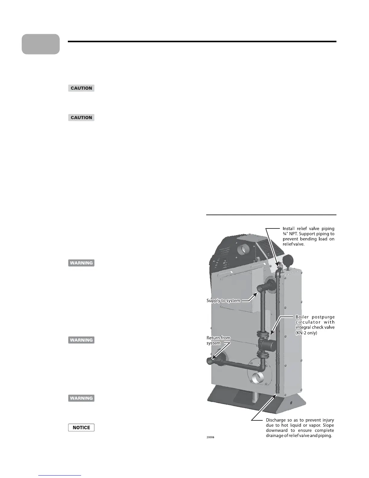
Figure 4 Relief valve piping
Prepare the boiler
Remove the boiler from the crate
Cold weather handling e boiler jacket
includes plastic parts. If the boiler has been in a cold
environment (below 0 °F), allow the boiler to warm
to room temperature before handling.
Do not drop the boiler or allow the jacket to bump
against the oor or wall when handling.
Remove the crate from the skid. But leave the boiler on the
skid to move the boiler near its location.
Inspect the boiler thoroughly for any possible damage that
may have occurred in shipping or handling.
Slide the boiler o of the skid into position.
Use a spirit level to check whether the boiler sides and front
are vertically plumb. If not, slide metal shims under the base
until the boiler is level.
Install the relief valve
Check relief valve pressure setting
Inspect the boiler relief valve before installing to ensure it is set at
the pressure required for the system. You should also verify that
all water system components are rated for at least the pressure
se ing of the relief valve to avoid component damage due to
excess pressure.
e boiler maximum allowable working
pressure is 100 psig (700 kPa). e relief valve
must never have a se ing greater than 100 psig.
Using a higher pressure relief valve could result
in an explosion, causing possible severe personal
injury, death or substantial property damage.
Connecting the relief valve
Connect ¾-inch NPT black iron pipe and ing so the relief
valve as shown in Figure 4. Follow all instructions provided in
the relief valve manufacturer’s instructions and labeling.
Never install any type of valve between the boiler
and the relief valve, or in the relief discharge
piping. An explosion could occur, causing severe
personal injury, death or substantial property
damage. General piping requirements.
Boiler piping — general
Improper piping of the boiler will void the
manufacturer’s warranty, and can cause boiler
failure, resulting in possible severe personal
injury, death or substantial property damage.
Install a shut-o valve in the boiler supply and
return connections to allow isolation of the
boiler for servicing when necessary.
1.
2.
3.
4.
Piping guidelines:
All installations must be installed by a quali ed technician
in accordance with the latest revision of the ANSI/ASME
Boiler and Pressure Vessel Code, Section IV.
Where required, the installation must comply with ANSI/
ASME CSD-1, Standard for Controls and Safety Devices
for Automatically Fired Boilers.
All applicable local codes and ordinances must also be
followed.
A minimum clearance of 1 inch (25 mm) must be main-
tained between heating system pipes and all combustible
construction.
All heating system piping must be supported by suitable
hangers not by the boiler.
e thermal expansion of the system must be considered
when supporting the system.
A minimum system pressure of 12 psig (84 kPa) must be
maintained.
•
•
•
•
•
•
•
4



 To Next Page