P/N 42-9450 8/08 Copyright 2008 Hydrotherm
Page 9 KN INSTALLATION AND OPERATION INSTRUCTIONS
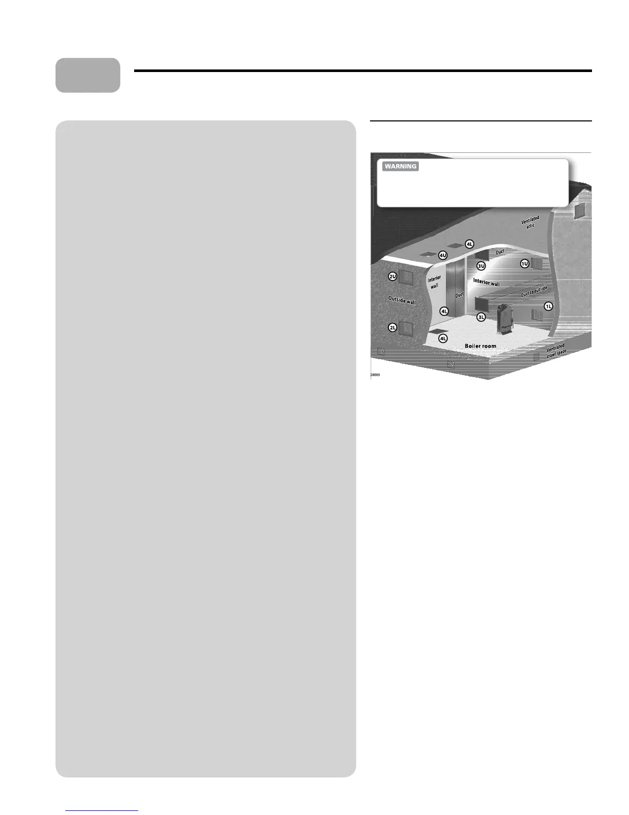
Figure 3 Air opening options for combustion air
drawn from boiler room
Installation site preparation (continued)
Combustion air requirements
Air ducted to boiler air intake
If air is ducted from outside to the boiler air intake, follow instructions in the
KN Vent/Air manual to size and install the air piping.
If the boiler is located in a small room (clearances less than the recommended
SERVICE/OPE TION clearances given in Figure 2, page 7):
No other appliances in the room Provide two ventilation openings
through one of the enclosure walls. Each opening must be sized for a free
area of at least 1 square inch per 1,000 BTUH input of the KN boilers in
the room. One opening must be within 12 inches of the ceiling, the other
within 12 inches of the oor.
Other appliances in the same room e room must have combustion
air openings sized for the other appliances. Increase the free area of the air
openings by one square inch per 1,000 BTUH of the KN boilers located
in the room.
Air from boiler room
When the boiler draws combustion air from the boiler room:
If the room volume is at least 50 cubic feet per BTUH of the combined
input of all appliances in the room, no special openings are needed
UNLESS the building is of tight construction (see de nition). If the
building is of tight construction, provide openings to the building in
accordance with all applicable codes.
If the boiler is in a space smaller than 50 cubic feet volume per BTUH
input, provide air openings using one of the methods in Figure 3.
De nitions
Free area Louvers or grilles reduce the area of an opening. Free area is the
area remaining with the louver or grille in place. If the free area of a louver is
unknown, use the following:
Metal louver Multiply required free area of the opening times 1.7 to
determine actual area of the required opening.
Wood louver Multiply required free area of the opening times 5 to
determine actual area of the required opening.
Tight construction When a building is extensively sealed to prevent air
in ltration, it cannot provide enough air for combustion unless openings are
provided to the outside. e National Fuel Gas Code de nes such buildings as
having all of the following:
Walls and ceilings exposed to the outside atmosphere have a continuous
water vapor retarder with a rating of 1 perm or less with openings
gasketed.
Weather-stripping has been added on openable windows and doors.
Caulking or sealants are applied to areas such as joints around windows
and door frames, between sole plates and oors, between wall-ceiling
joints, between wall panels, at penetrations for plumbing, electrical, and
gas lines, and in other openings.
Conversion factors
In
2
/1,000 BTUH to cm
2
/kw Multiply In
2
/1,000 BTUH times 22
In
2
/2,000 BTUH to cm
2
/kw Multiply In
2
/2,000 BTUH times 11
In
2
/3,000 BTUH to cm
2
/kw Multiply In
2
/3,000 BTUH times 7.4
In
2
/4,000 BTUH to cm
2
/kw MultiplyIn
2
/4,000 BTUH times 5.5
•
•
•
•
•
•
•
•
•
Upper openings (U) must be within 12 inches of the ceiling. Lower
openings (
L) must be within 12 inches of the oor.
Option 1 —
air openings through interior wall
When air is supplied to the boiler room through openings in an
interior wall (air supply from inside the building), size each opening to
provide minimum free area of:
1 in
2
per 1,000 BTUH of all KN boilers in the room.
Option 2 —
air openings through outside wall
When air is supplied to the boiler room through openings in an
outside wall (air supply from outside the building), size each opening
to provide minimum free area of:
1 in
2
per 4,000 BTUH of all KN boilers in the room.
Option 3 — horizontal ducts to outside wall
When air is supplied to the boiler room through horizontal ducts to an
outside wall (air supply from outside the building), size each opening
to provide minimum free area of:
1 in
2
per 3,000 BTUH of all KN boilers in the room.
Option 4 —
openings to attic/crawl space
Air openings can be connected to a ventilated a ic or crawl space. e
upper opening must be to the a ic. e lower opening can be a vertical
duct from the a ic or an opening in the oor from the crawl space. Size
each opening to provide minimum free area of:
1 in
2
per 3,000 BTUH of all KN boilers in the room.
Option 5 —
single opening (not shown)
A single opening directly connected to the outdoors through a wall or
a vertical or horizontal duct can be used if the installation provides the
clearances of Figure 2, and the top of the opening is within 12 inches of
the ceiling. Size the opening to provide minimum free area of:
1 in
2
per 3,000 BTUH of all KN boilers in the room.
If other appliances are located in the same room
as the boiler, increase the size of air openings
to provide the free area required for the other
appliances in addition to the air required for the
KN boiler(s).
3