P/N 42-9450 8/08 Copyright 2008 Hydrotherm
Page 20 KN INSTALLATION AND OPERATION INSTRUCTIONS
Wiring a single boiler
7
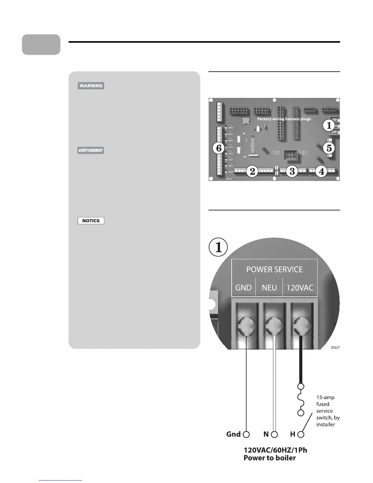
Figure 15 Electrical connection board (see item 10,
page 3 for location — Also see the wiring
summary illustrations on the next pages)
Figure 16 120VAC power service terminals on
electrical connection board — See Figure 15
for location of the power terminal strip
Electrical shock hazard —
Disconnect all electrical power sources
to the boiler before making any electrical
connections.
Label all wires prior to disconnection
when servicing controls. Wiring errors
can cause improper and dangerous
operation! Verify proper operation a er
servicing.
Au moment de l’entretien des com-
mandes, étiquetez tous les ls avant de
les débrancher. Des erreurs de câblage
peuvent entraîner un fonctionnement
inadéquat et dangereux. S’assurer que
l’appareil fonctionne adéquatement une
fois l’entretirn terminé.
Failure to comply with the above could
result in severe personal injury, death or
substantial property damage.
e electrical connections to this boiler
must be made in accordance with all
applicable local codes and the latest
revision of the National Electrical Code,
ANSI /NFPA-70. Installation should
also conform to CSA C22.1 Canadian
Electrical Code Part I if installed in
Canada. Install a separate 120 volt 15
amp circuit for the boiler. A properly
rated shut-o switch should be located at
the boiler. e boiler must be grounded
in accordance with the authority having
jurisdiction, or if none, the latest revision
of the National Electrical Code, ANSI/
NFPA-70.
Line voltage eld wiring of any controls
or other devices must use copper
conductors with a minimum size of #14
awg. Use appropriate wiring materials
for units installed outdoors.
General
e wiring and control information in the Boiler manual is
targeted at single-boiler, stand-alone installations. For mul-
tiple boilers and advanced options, see the KN Control
manual.
See Figures 20 and 21 for a wiring summary. See the Control
manual for content not covered in this manual.
Power supply (120 VAC)
See Figures 15 and 16.
Connect minimum 14awg copper wire to the power
connection as shown in Figure 16.
Install a fused service switch, mounted and installed in
accordance with all applicable codes.
•
•
•
•
•



 To Next Page