P/N 42-9450 8/08 Copyright 2008 Hydrotherm
Page 13 KN INSTALLATION AND OPERATION INSTRUCTIONS
Water piping (continued)
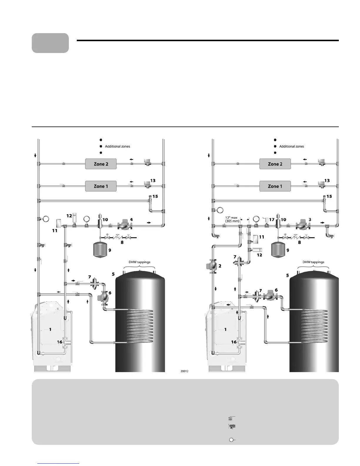
Figure 8 Suggested piping — single boiler — zone valve zoning — two-pipe or series loop (left), or primary/secondary piping (right)
LEGEND • • • • • • •
1 KN boiler
2 Boiler circulator
3 System circulator
4 Boiler/system circulator
5 Indirect- red DHW tank
(when used)
6 DHW circulator
7 Flow/check valve
8 Cold water ll line
9 Expansion tank (shown with diaphragm-type — see
page 12 for piping a closed-type tank)
Expansion tank (shown with diaphragm-type — see
page 12 for piping a closed-type tank)
10 Air separator with automatic air vent (Replace air vent
with piping to the tank ing on closed-type expansion
systems.)
11 Low water cut-o (when required)
12 Extra high limit (when required)
13 Zone valve
14 Zone circulator
15 Di erential pressure by-pass valve — Use when high-
head circulator may cause noise, erosion or valve li ing
problems when only a few zone valves are open.
16 Boiler postpurge circulator (see page 11) KN
-
2 only
17 Header sensor, required where shown
Isolation valve
Purge valve — Suggested locations allow for improved
system lling and draining and initial air elimination.
Temperature gauge
Zoning with zone valves
Flow balancing and control
On large systems, or when using a high-head circulator, install a di erential
pressure by-pass valve to limit the head applied to the zone valves.
Some systems may require balancing valves to control ow in the loops.
DHW operation, when required
e piping shown throughout this manual allows for domestic water
heating without ow through the heating loop(s). is is important for
summertime operation of DHW tanks.
Make sure to incorporate ow/check valves as shown. ese prevent forced
ow in idle zones.
5
*
**
 Loading...