P/N 42-9450 8/08 Copyright 2008 Hydrotherm
Page 19 KN INSTALLATION AND OPERATION INSTRUCTIONS
Gas piping (continued)
Table 3 Gas ow capacity for black iron pipe
Iron
pipe
size
(inches)
Pipe length, equivalent feet (length plus allowance for ttings)
10 20 30 40 50 60 80 100 150
Natural gas pipe ow capacity
(cubic feet per hour) (note s 1, 2, 3)
¾ 278 190 152 130 115 105 90 79 64
1 520 350 285 245 215 195 170 150 120
1 ¼ 1050 730 590 500 440 400 350 305 250
1 ½ 1600 1100 890 760 670 610 530 460 380
Propane gas pipe ow capacity (cubic feet per hour) (n ot es 2, 3)
¾ 172 118 94 81 71 65 56 49 40
1 320 220 175 150 135 120 105 95 75
1 ¼ 650 455 365 310 275 250 220 190 155
Notes, Table 3
1
2
3
Natural gas ow capacity is based on 0.60 speci c gravity. Refer to the National Fuel Gas Code, ANSI
Z223.1/NFPA 54, for other pressure drops and other speci c gravity gases.
e ow rates above allow for a pressure drop of:
Natural gas — 0.30 inches water column, with gas pressure 14 inches water column or less.
Propane — 0.30 inches water column, with gas pressure 14 inches water column or less.
To determine required ow rate in cubic feet per hour for all appliances connected to the gas line:
Natural gas — Divide total Btuh by the gas Btu per cubic foot rating (typically 1,000 Btu/
3
nominal).
Propane — Divide total Btuh by 2,500.
Table 4 Equivalent feet of pipe for common gas line components
Iron
pipe
size
(inches)
Equivalent feet of pipe for each tting
90° Elbow Tee
(n ot e 1)
Gate valve
(n ot e 2)
Gas cock
(note 2)
1” 2.6 5.2 0.6 1.5
1 1/4” 3.5 6.9 0.8 1.9
1 1/2” 4.0 8.0 0.9 2.3
2” 5.2 10.3 1.2 3.0
Notes, Table 4
1
2
Allows for ow through the branch of the tee.
Assumes valve is full open.
Gas piping joints
Always use a pipe sealant that is suitable for use
with LP gas. Failure to comply could result in
an explosion, causing possible severe personal
injury, death or substantial property damage.
Only use pipe dope listed for use with propane gas. Even natural
gas may contain some amount of propane.
Use pipe dope sparingly. Excessive pipe dope can block pipe
ow or foul gas train components.
Gas pipe sizing
Required supply pressure at boiler
Minimum gas supply pressure (natural gas or propane), both for
owing and static conditions:
2 inches (102 mm) water column.
Maximum gas supply pressure (natural gas or propane), both
for owing and static conditions:
14 inches (356 mm) water column.
Sizing guidelines
e sizing recommendations of Table 3 are taken from the
National Fuel Gas Code, ANSI Z223.1/NFPA 54. Propane
values are based on adjustment from propane speci c gravity
and pressure.
Table 3 allows for a pressure drop from the main supply regulator
to the boiler of 0.3 inches (7.6 mm) water column for natural gas
or propane.
For conditions not shown in Table 3, other pressure drops,
or natural gas with other than 0.6 speci c gravity, refer to the
appropriate code guidelines for sizing.
Equivalent length
Do not neglect the pressure drop due to pipe ings.
Equivalent length is the sum of the actual length of piping plus
the total equivalent lengths of all ings in the line from the
main regulator to the boiler connection. See Table 4 for equiva-
lent lengths of common ings and components.
Multiple appliances
If more than one appliance is supplied by the same supply
pipe, the piping must be sized based on the maximum possible
demand.
Undersized gas supply piping can cause the
gas line pressure to become negative during
operation of the KN boiler. is can cause pilot
outages and operation failures of other appliances
connected to the line, including gas ranges, water
heaters, etc. Failure to properly size the gas lines
can result in potential for severe personal injury,
death or substantial property damage.
Test all gas piping for leaks
All gas piping, components and connections must be leak tested
before pu ing the boiler in operation. Isolate the boiler from the gas
supply piping if testing with pressure greater than 14 inches (12.7 mm)
pressure. Failure to do so could result in severe personal injury, death or
substantial property damage.
Check all gas piping components and joints for
leaks. Use either a soap suds mixture, a gas leak
detector or other suitable means.
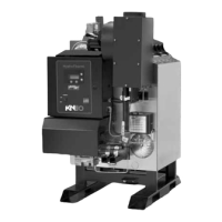
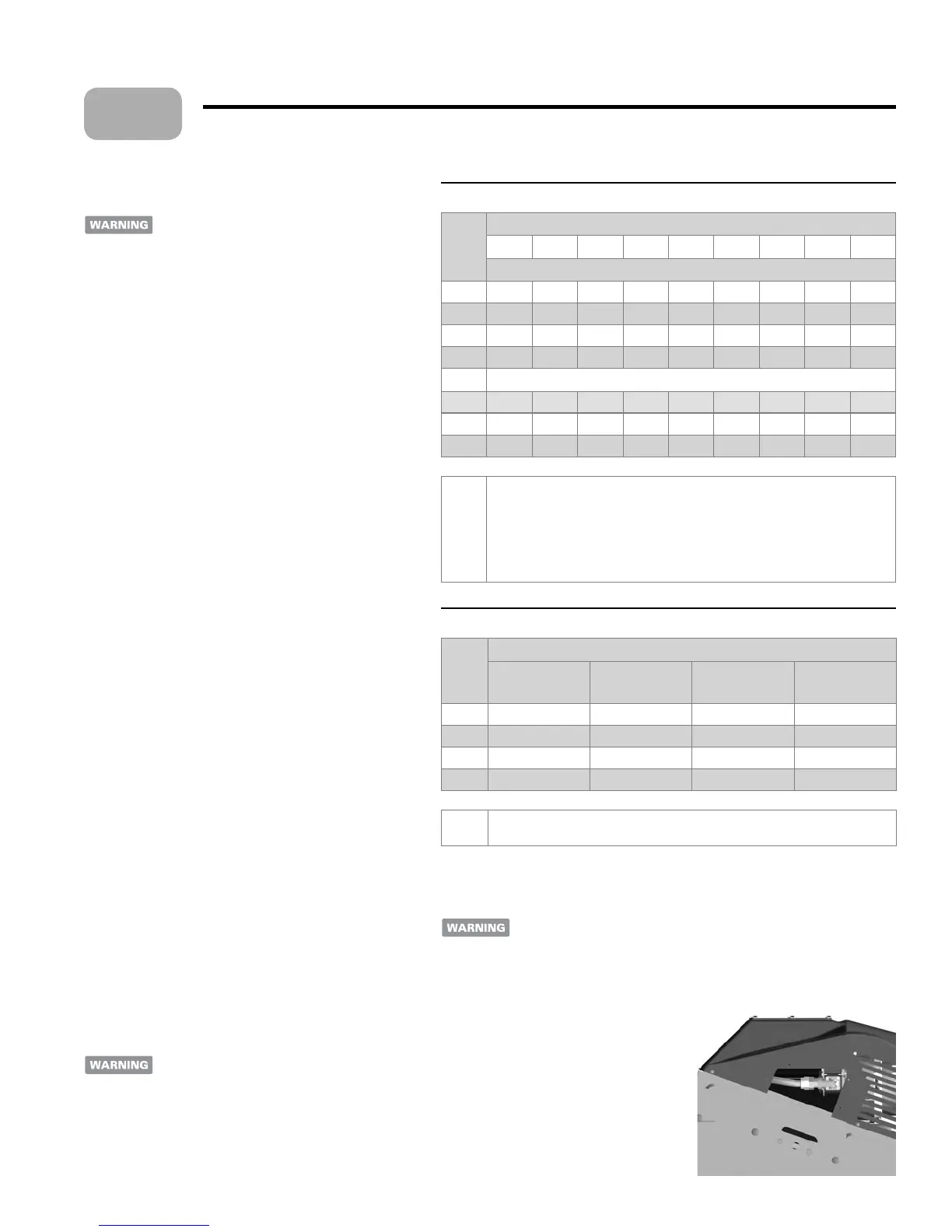
A er testing the system gas piping, remove
the gas valve cover plate on the le side of the
boiler (see illustration at right). Inspect and
leak test around the interior gas line and gas
valve. Replace the cover a er completing the
gas connection inspection and testing.
6
 Loading...