P/N 42-9450 8/08 Copyright 2008 Hydrotherm
Page 3 KN INSTALLATION AND OPERATION INSTRUCTIONS
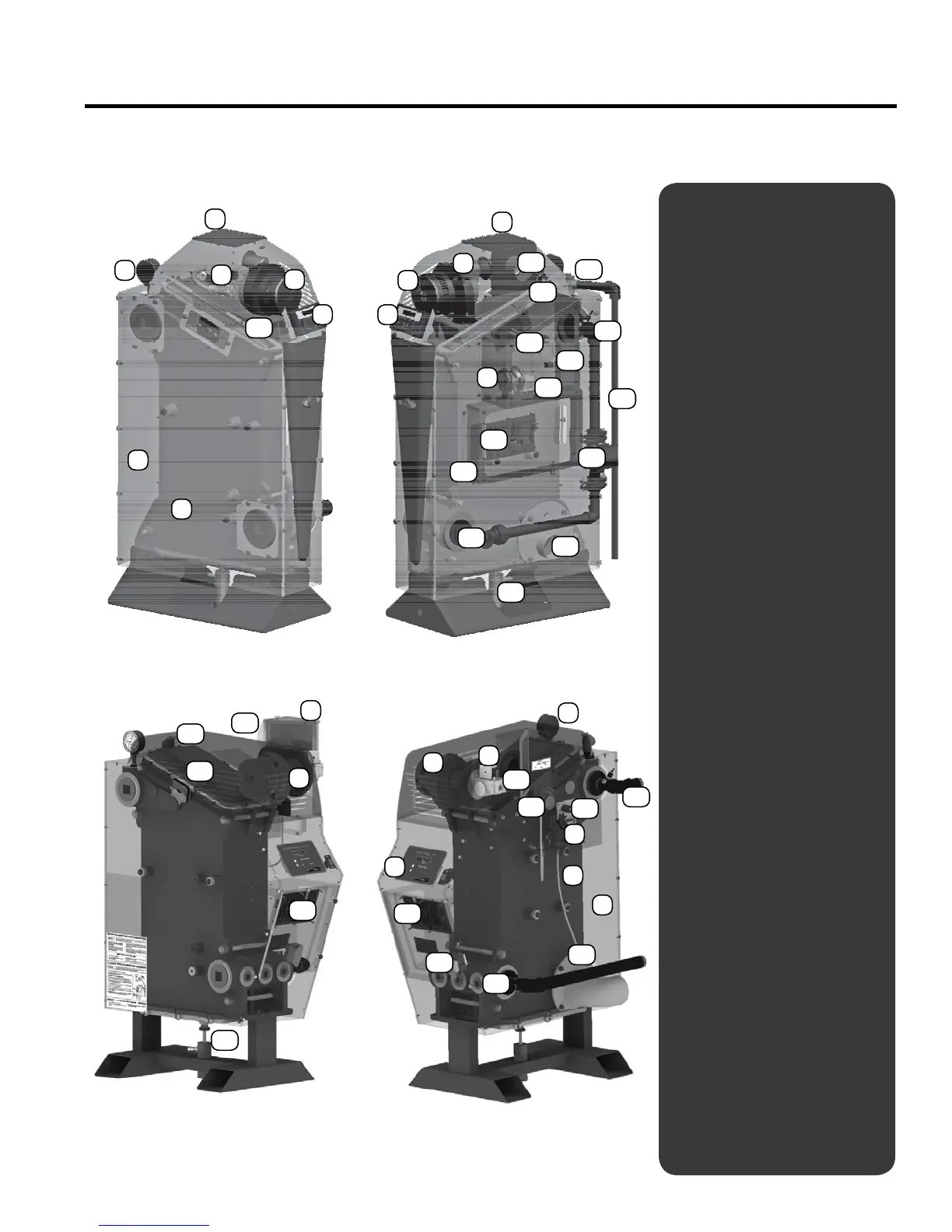
KN
components
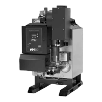
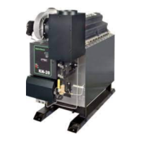
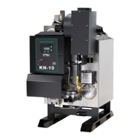
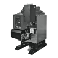
Components
Gas valve
Pressure/temperature
gauge
Jacket
Cast iron section assembly
Inlet air lter access panel
Blower
7.
KN HeatNet
TM
control with
keypad and display
8. Venturi assembly
9. Pressure switches (blocked
ue and blocked air inlet)
10. Control connection board
11. Electrical box (power and
control entrances)
12. Water return connection
13. Air inlet sleeve
14. Relief valve
15. Relief valve piping (by
installer)
16. Water supply connection
17. Fenwal ignition module
18. Ignition electrodes/ ame
rod assembly
19. Control transformer (120/24
VAC)
20. Postpurge circulator, fac-
tory-installed and piped
21. Vent connection sleeve
(with ue gas sampling
port)
22. Condensate tubing connec-
tion
23. Upper section cover and
premix burner
24. Gas connection, ½” NPT
1.
2.
3.
4.
5.
6.
The Hydrotherm KN condensing cast iron boiler
KN
-
22
21
12
11
3
4
2
5
5
1
6
6
7 7
8
9
13
14
16
15
24
20
18
23
10
19
17
12
21
16
17
18
24
10
19
6
1
2
4
3
9
7
22
23
14
11
13
5
8