P/N 42-9450 8/08 Copyright 2008 Hydrotherm
Page 34 KN INSTALLATION AND OPERATION INSTRUCTIONS
Figure 24b Boiler sequence of operation, fault states and HeatNet control display information
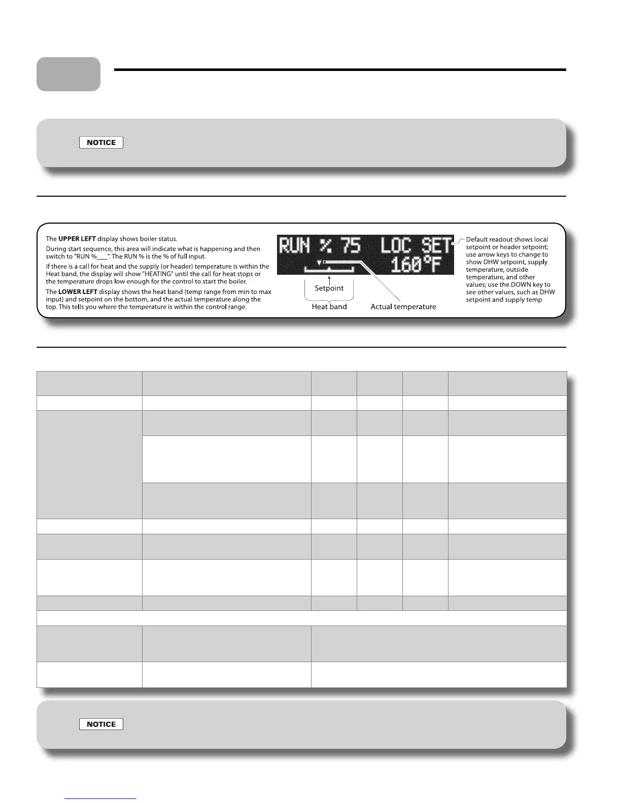
Figure 24a HeatNet control display during operation
Starting the boiler (continued)
Normal condition Blower status Time Ignition
status
Gas valve
status
Display
(upper left)
Standby (not heat call) OFF
OFF OFF
STANDBY
Start (call for heat) OFF (Flow switch and other interlocks in
the ow switch circuit must prove)
10 seconds OFF OFF
FLOW WAIT
OFF
if supply temperature is above the
bottom of the heat band; circulator runs,
but boiler does not re yet
Demand OFF OFF
HEATING
ON at purge RPM (55% of maximum)
when supply temperature drops below
the bottom of the heat band
10 seconds
PRE PURGE
Ignition trial ON at ignition RPM (30% of maximum)
4 seconds ON ON
IGN 30%
Flame is sensed
(Stabilization period)
ON at ignition RPM (30% of maximum)
6 seconds OFF ON
IGN 30%
Operate on demand ON at RPM based on demand (control
determines ring rate % based on
demand and rate of change, etc.)
Demand OFF ON
RUN %XXX
End call for heat ON at purge RPM (55% of maximum)
OFF OFF
POST PRGE
Ignition failure ON at purge RPM
Boiler restarts a normal sequence
Control will try 3 times, then lockout
Normal display unless three attempts fail, then shows:
IGN LOCKOUT
(alternating to:)
Date & Time of lockout
Flame failure ON at purge RPM for postpurge
Boiler restarts a normal sequence
Normal display unless ignition is unsuccessful three times after
restart
To reset the HeatNet control from lockout: Turn the boiler on/o switch OFF, then back ON.
For more information: See the KN Control manual for additional information and troubleshooting.
12
 Loading...