P/N 42-9450 8/08 Copyright 2008 Hydrotherm
Page 43 KN INSTALLATION AND OPERATION INSTRUCTIONS
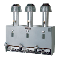
Cleaning the air lter
Turn the boiler on/o switch OFF.
Remove the three thumb screws that secure the lter access
plate (see Figure 33).
Remove the lter access plate and gasket.
Pull the lter clamp back and remove the air lter.
Inspect the lter and the lter enclosure area for dust or
debris.
Clean the lter, if necessary, by washing under running wa-
ter. Shake o excess water and towel dry.
If the lter enclosure and blower inlet show
signs of drywall dust, construction debris or
other deposits, you may need to inspect the
burner. Follow the procedure in this section.
Accumulation of debris in the burner can result in
burner damage and potential for severe personal
injury, death or substantial property damage.
7. If the lter is damaged or cannot be cleaned e ectively,
obtain a replacement lter from your boiler distributor.
8. To replace the air lter, pull the lter clamp back, insert the
lter, and allow the clamp to secure the lter in place.
9. Replace the lter access cover gasket and access cover.
10. Replace the three thumbscrews and nger tighten securely.
11. Turn the boiler on/o switch ON.
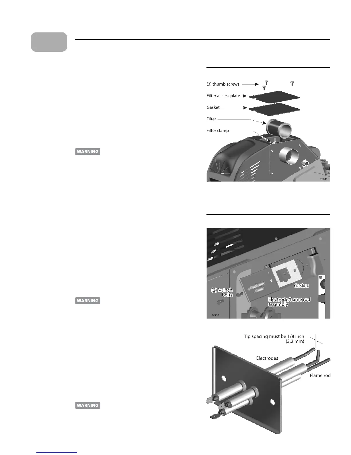
Accessing the electrode assembly
Turn the boiler on/o switch OFF.
If the boiler ignition electrodes or ame rod appear to be
operating incorrectly, remove and inspect the assembly as
follows.
Do not remove the electrode assembly while the
boiler is operating. Allow the boiler and electrode
assembly to cool before a empting removal to
avoid possible burns. Failure to comply could
result in severe personal injury.
3. With the boiler and manual gas valve closed, remove the
upper electrical box cover (right side of boiler).
Remove the two ¼ inch bolts that secure the electrode/
ame rode assembly to the boiler (Figure 34).
e electrode spacing must be 1/8 inch (3.2 mm) as shown
in Figure 26.
4. If the electrodes or ame rod are damaged or the tip spacing
is incorrect, replace the assembly. e electrodes are
NOT
adjustable.
5. Re-install the assembly in the boiler.
Make sure the electrode plate gasket is in good
condition and that the assembly is securely
bolted to the boiler. e combustion chamber
operates with a positive pressure. Failure to
comply could result in severe personal injury,
death or substantial property damage.
1.
2.
3.
4.
5.
6.
1.
2.
•
•
Maintenance (continued)
13
Figure 33 Accessing the air lter
Figure 34 Electrode/ ame rod assembly inspection
 Loading...