Do you have a question about the Hydrovane HV22 and is the answer not in the manual?
Full support is available from your Hydrovane Distributor. Contact them for specialist help or service.
Guaranteed for 12 months from commissioning or 18 months from shipment. Excludes wear items and consequential damage.
Hydrovane adopts a policy of continual product development. Information may change without notice.
Hydrovane Quality Management Systems approved to BS EN ISO 9001. Complies with European Directives.
This handbook relates to ACE HV04-HV45 vertical range compressors and hypac models.
Explains the segments of the product code and their meaning.
Instructions to follow before installation, operation, maintenance or repair of the compressor unit.
Ensuring compliance with the Act by using competent persons and following handbook instructions.
Precautions to take before performing any work on the compressor, including isolation and pressure relief.
Guidelines for safe operation, including warnings about hot surfaces and compressed air.
Hazards associated with Hydrovane approved oil, including skin irritation and recommended precautions.
Procedures for inhalation, skin contact, eye contact, and ingestion of oil or related substances.
Explanation of warning symbols (WARNING!, CAUTION!) and their significance.
Describes optimal operating temperatures for performance and service life.
Discusses reasons for high temperatures and automatic shutdown limits.
Notes on sound pressure levels and recommended positioning.
Detailed technical specifications for HV04, HV05, HV07, and HV07RS models.
Detailed technical specifications for HV11, HV15, HV18, HV22, and their RS variants.
Detailed technical specifications for HV30, HV37, HV45, and their RS variants.
Guidance on carrying out lifting and transportation by authorised, trained personnel.
Details on using fork lifts, pallet trucks, and avoiding damage during movement.
Table showing weights for various ACE HV04-HV45 compressors and hypac models.
Guidelines for siting the compressor/hypac, including space, levelness, and environment.
Instructions on positioning for optimal cooling air-flow and avoiding re-circulation.
Warning about qualified electricians and ensuring the supply meets load requirements.
Detailed steps for connecting the compressor to the mains electrical supply via an isolator.
Procedure to verify correct motor rotation to prevent damage.
Specific installation guidance for regulated speed compressors.
How to operate RS compressors efficiently with other Hydrovane units.
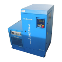
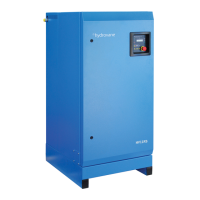
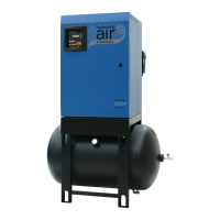
Overview of the ACE HV04-HV45 vertical range and hypac units.
Describes operating modes: Automatic Stop/Start, Continuous Run, and Regulated Speed.
Detailed breakdown of the compressor unit components and their arrangement.
Explanation of the electronic controller's menu structures and access levels.
Overview of operating instructions and safety warnings for authorised personnel.
Essential checks to perform before starting the compressor.
Describes controller display, LED indicators, and basic operation.
Steps for starting the compressor in automatic mode and its behaviour.
Steps for starting the compressor in continuous run mode.
Starting procedure for variable speed models.
Procedure for safely stopping the compressor.
How to use the emergency stop button and subsequent actions.
Explanation of the automatic compressor vent down process.
Explanation of symbols displayed on the controller for operational status.
Description of LED indicators and their meanings in different states.
Overview of the Customer Menu (P10) for parameter settings.
How to access and modify parameters in the Customer Menu.
Instructions for setting the operating mode to Automatic or Continuous.
Procedure for adjusting load and unload pressures for single speed units.
Adjusting pressure settings for RS compressors.
Procedure for adjusting the servo valve for pressure control.
Safety precautions and overview of servicing requirements.
Details the minimum service requirements and recommended intervals.
Servicing intervals for RS units are the same as fixed speed units.
How to check compressor temperature and pressure during operation.
Procedure to access and view the compressor pressure gauge.
Instructions for checking the oil level using the sight glass.
Steps for performing a basic service, including isolation and safety checks.
How to remove the top panel for access to internal components.
Procedure for draining oil and replacing the oil filter.
Detailed steps for draining the compressor oil.
Instructions for removing and fitting a new oil filter.
Procedure for filling or topping up the compressor oil level.
Steps for replacing the air filter element.
Procedure for replacing the oil separator.
Instructions for cleaning the oil cooler and aftercooler matrix.
How to remove and replace the cabinet air filter.
Steps for refitting panels after servicing.
Safety precautions and checks for electrical connections.
Instructions for cleaning the motor and air intake.
Overview of preventive maintenance charts and service intervals.
Details service schedules based on oil type and operating conditions.
List of additional kits available for full product support.
General information on how the controller monitors faults and identifies error types.
List of shutdown error codes and their meanings.
List of alarm error codes for warnings that do not stop the compressor.
Error codes that prevent the motor from starting.
Alarm indicating that routine service is due.
Explanation of symbols appearing on the controller display with fault codes.
Overview of controller menus and access restrictions.
Menu configured for oil changes as part of a service agreement.
Menu for authorised engineers for installation or maintenance.
Menu for checking and testing controller inputs and outputs.
Menu for matching inverter drive and motor control features.
Master configuration menu for default settings.
| Model | HV22 |
|---|---|
| Type | Rotary Vane |
| Motor Power | 2.2 kW / 3 hp |
| Free Air Delivery | 21 cfm / 595 l/min |
| Weight | 141 kg |
| Noise Level | 69 dB(A) |
| Power | 22 kW |
| Air Flow Rate | 3.7 m³/min |
| Max Pressure | 10 bar |
| Tank Capacity | Not Applicable |