24 Duramax/Duramax Hyamp Robotic Torches Service Manual 807460
2 – Torch Setup
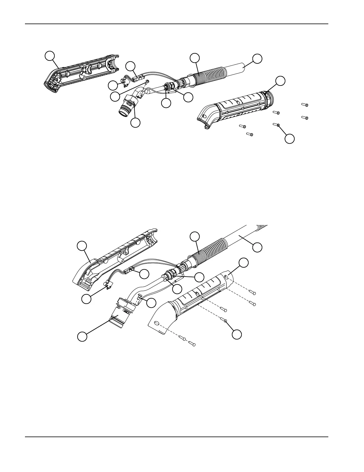
Figure4–Duramax 45°
Figure 5 – Duramax Hyamp 45°
1 Right half of the positioning barrel
2 Cap-sensor switch connector
3 Cap-sensor switch
4 Pilot terminal screw
5 Torch body (torch head and gas tube)
6 Gas supply tube fitting
7 Gas fitting flange
8 Positioning barrel screws (6)
9 Left half of the positioning barrel
10 Torch lead
11 Strain relief
1 Right half of the positioning barrel
2 Cap-sensor switch connector
3 Cap-sensor switch
4 Pilot terminal screw
5 Torch body (torch head and gas tube)
6 Gas supply tube fitting
7 Gas fitting flange
8 Positioning barrel screws (6)
9 Left half of the positioning barrel
10 Torch lead
11 Strain relief