12
Table motion sequence
Refer to Figure 10 for an illustration of the following sequence.
1 After transfer, the table motion begins for the first segment at a fast gouge
speed (the first “F” code) for the required segment length necessary to
establish the evacuation channel (or trough).
2 The second segment table motion begins at an intermediate speed (second
“F” code) for the required segment length necessary to penetrate the plate.
3 The third segment of table motion begins at the programmed cut speed. The
remainder of the cut is completed at this speed (third “F” code).
4 Finally, the contour cut of the part is completed.
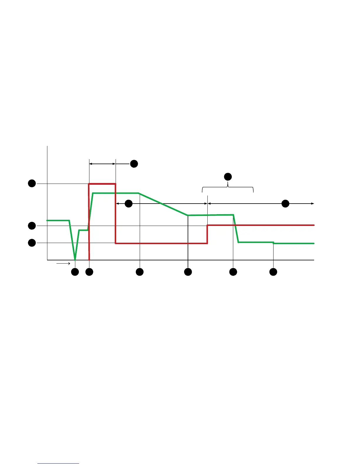
Figure 10 – Moving pierce table motion timing diagram
Feed rate
7
8
9
1
0
1
2
3
45
6
Time
1
2
1
1
1
3
1 Gouge speed
2 Cut speed
3 Creep or intermediate speed
4 Initial height sense
5 Arc transfer, motion begins, shield flow switches from preflow to cutflow
(if preflow is lower than cutflow)
6 Torch begins to lower toward pierce end height
7 Torch reaches pierce end height as pierce delay expires
8 Torch lowers to cut height as cut height delay expires
9 AVC begins as MP AVC delay expires prior to starting cut
10 Establishes evacuation trough
11 Penetration of plate advances while molten material is evacuated via trough
12 Arc penetrates plate in this region
13 Transition to cut speed as arc penetrates plate