Installation of Wheels to Powermax900
Kit: 128316
Page 3 of 3
7. Attach one of the casters (027299) to the right
chassis stiffener as shown in Fig. 2. Insert 4
screws (075472) through the bottom 4 holes of
the chassis stiffener from the outside of the
power supply as in the previous steps.
• Hand tighten 4 kepnuts to the screw ends
that protrude through the chassis floor.
• Using a 3/8" (10 mm) nut driver, tighten
the 2 upper chassis stiffener kepnuts and
the 4 caster kepnuts firmly.
8. Repeat steps 5 through 7 to mount the left
chassis stiffener (001528) and remaining caster.
(Chassis stiffener holes offset to the right)
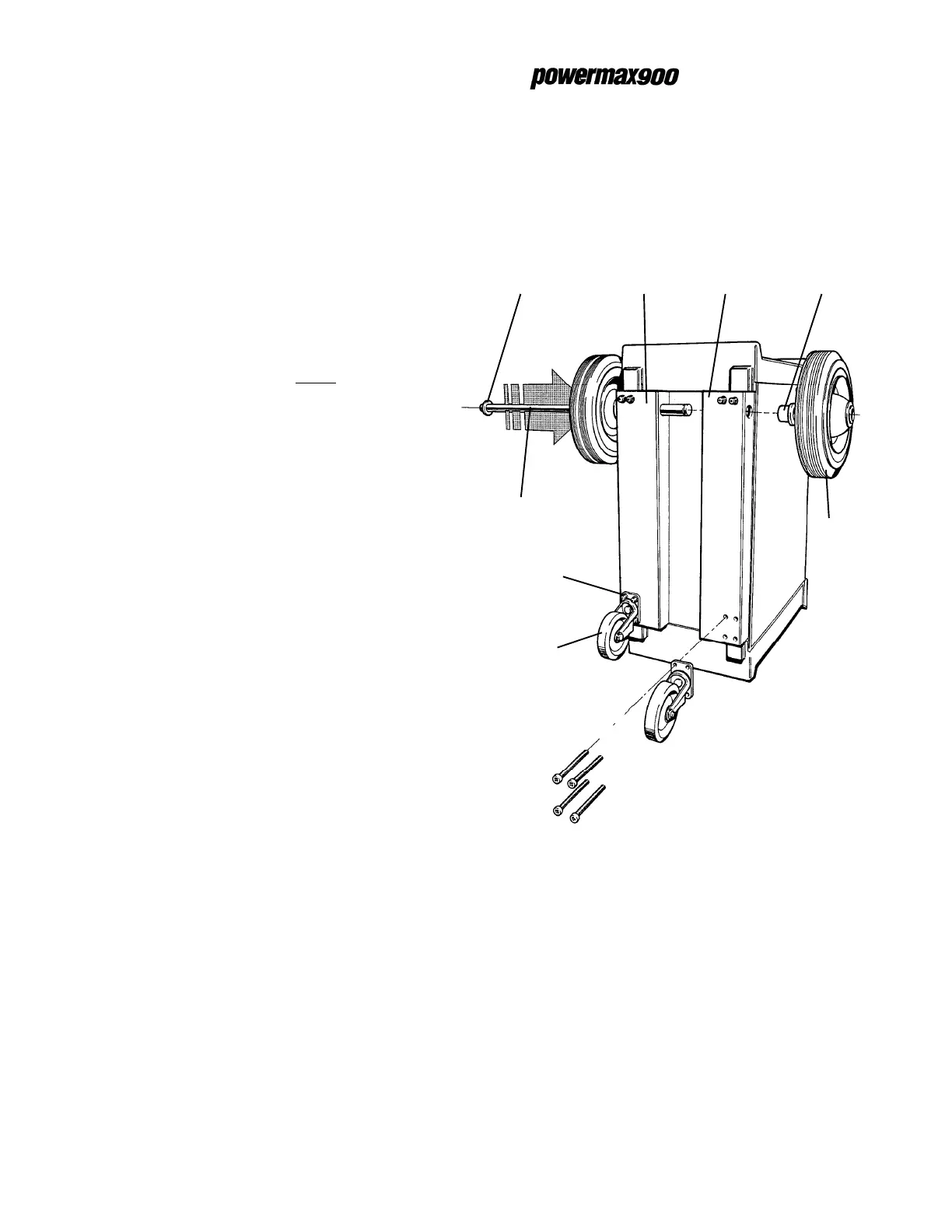
9. Snap a retaining ring (027249) on one end of
the axle (004672).
10. Slide one of the wheels (027057) onto the axle.
11. Slide one of the shoulder washers (008907)
over the end of the axle with the larger diam-
eter end of the washer facing the mounted
wheel.
12. Slide the axle through the axle hole in the right
chassis stiffener as shown in the figure.
13. Continue sliding the axle through to the axle
hole in the left chassis stiffener and mount the
other wheel as shown in the figure.
14. Tilt the power supply back on the wheels and
replace the power supply cover. Note that the
rear wheels interfere with the replacement of 2
of the power supply cover screws. It is not
necessary to insert these 2 screws.
Wheel installation is complete. See Powermax900
operator manual 803080 for further installation and
operation instructions.
Figure 2 Power Supply on Front Handles
Outside Bottom View
Right chassis
stiffener
001555
Left chassis
stiffener
001528
Shoulder
washer
008907
Retaining
ring
027249
Axle
004672
Wheel
027057
Caster
027299
Screws
075472
7-98