© 2016 www.hysecurity.com SlideDriver Installation and Assembly MX3629-01 Rev. B Page 7
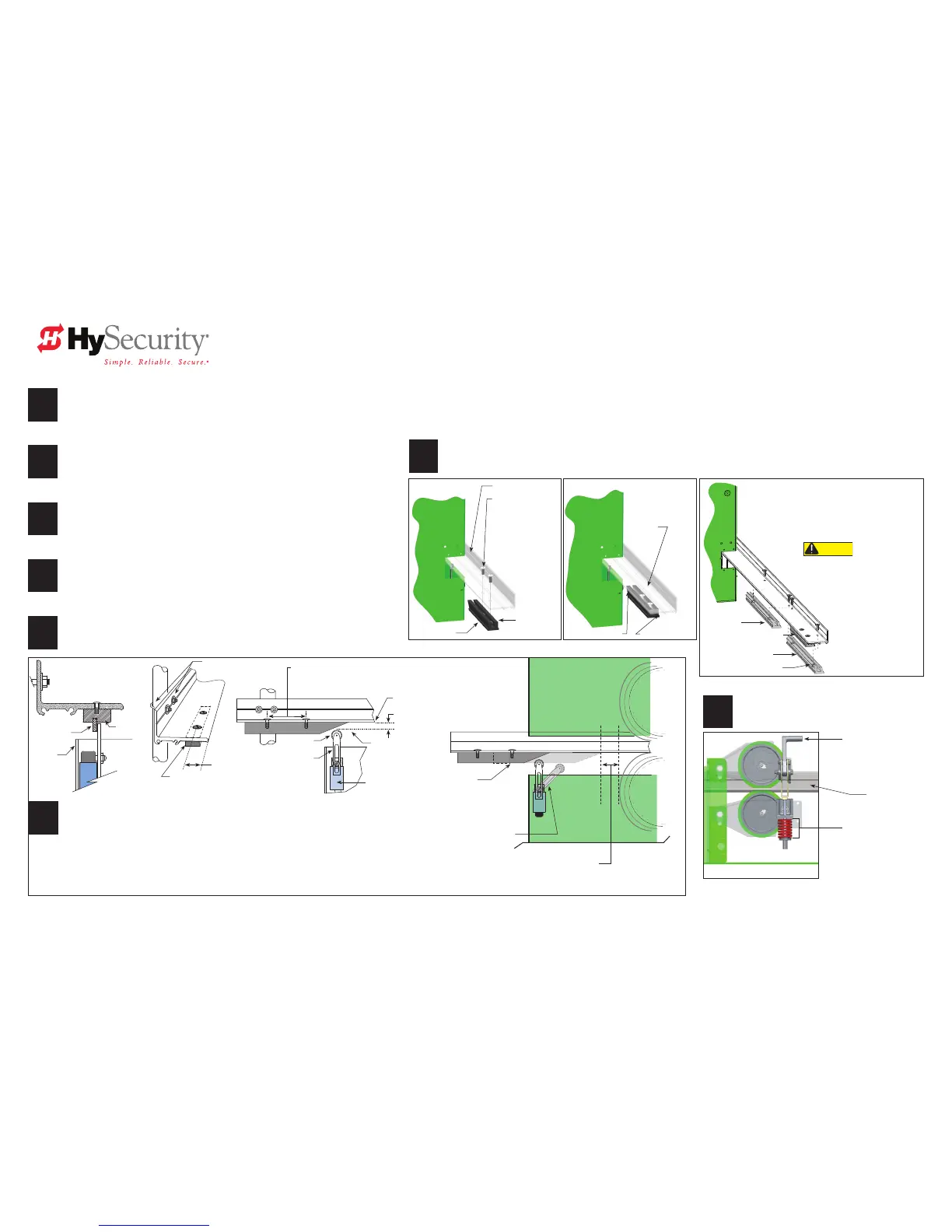
Install and Secure Limit Ramps
Drawings NOT to Scale
2
1
Determine Limit Ramp Location.
Position the gate fully-closed and mark the drive rail.
NOTE: The toggle handle needs to be in the "unclamped" position. See page 4.
Move the gate 6-inches (15 cm) from the fully closed position.
Determine where to place the Standard Limit Ramp so it will trip the limit switch
approximately 6-inches (15cm) before the exact spot where you want the gate to
stop (2-inches from the drive wheel).
4
3
Mark mounting holes.
Measure and mark the mounting locations for the truss head screws 1-inch (2.5 cm)
from the edge of the drive rail.
Drill one
⅜-inch (9.5 mm) mounting hole.
Place one nut in the limit ramp channel. Secure the Standard Limit Ramp by
inserting the screw through the drive rail and into nut. Finger-tighten.
6
5
Open and close the gate to check the position of the Standard Limit Ramp.
Make adjustments as necessary and drill the remaining mounting hole about
4-inches (10 cm) from the rst.
Secure the Standard Stop Limit Ramp to the drive rail with the fasteners provided.
NOTE: If you are installing a SlideDriver 50VF-series gate operator, align the angled edge of the Slow Down Limit Ramp
(MX3043 kit) with the edge of the Standard Limit Ramp. Secure it and the remaining limit ramps to the drive rail.
Before installing the limit ramps, review the illustrations on this page.
7
Adjust the limit switches.
To position the limit switch, loosen the height adjusting screw.
Move the limit switch arm up or down so the top of the roller is about ⅜-inch (9.5mm) from the
base of the drive rail.
Secure the limit switch arm by tightening the height adjusting screw. Perform the same steps on
the opposite end of the drive rail.
NOTE: Only the limit ramp should trigger the limit switch.
The Standard Limit Ramp is positioned on the drive rail so it will make contact with the limit switch and stop approximately 2-inches (5 cm)
from the drive wheel.
• Limit ramps are attached to the underside of the drive rail when the gate is fully open and fully closed.
Limit ramps install to both ends of the drive rail.
• Two truss head screws secure each limit ramp to the drive rail. The screws are spaced about 4-inches (10 cm) apart.
Drive Rail
Standard Stop
Limit Ramp
Nut
Truss head ⅜-inch
(9.5 mm) screws.
Must be fully tightened
and ush before
adjusting
Limit Switches.
CAUTION
Be sure to securely fasten all limit
ramps to the underside of the drive rail
at both ends (gate fully open and fully
closed). Failure to do so will void the
Warranty.
Align one angled edge of the Slow Down Limit Ramp with
the edge of the Standard Limit Ramp.
Make sure its opposite angled edge nests against the
remaining limit ramp.
Order 4 Limit Ramp kits for 50VF gate operators: MX3043
Slow down
Limit Ramp
Slow down
Limit Ramp
Standard Stop Limit Ramp
Nuts inside limit ramps
SlideDriver50VF models add Slow Down Limit Ramps
8
Clamp drive wheels.
Refer to page 6 for WARNING. Place toggle
handle in clamped (load) position.
Toggle Handle Assembly
Compression spring set at
2-inches (5 cm) when drive
wheels are clamped on
drive rail.
Truss head
screws ush on
drive rail
Edge of Drive Rail End of Drive Rail
Articulating arm
(Tripped position)
Limit Ramp
enters chassis cutout
Drive Wheel
Drive Wheel
2-inches (5 cm)
Limit ramp stopped position
1-inch (2.5 cm)
Standard Stop
Limit Ramp
Height adjusting screw
Articulating arm
(Normal position)
Roller
4-inches (10 cm)
Spacing between screws (approximate)
U bolt and fasteners
⅜-inch (9.5mm)
Base of drive rail
Limit Switch
inside chassis
Angled edge of
Limit Ramp faces
chassis cutout
and drive wheels
Roller
Chassis
Limit
Ramp
Drive Rail
Toggle handle
Stop Limit Ramp on all SlideDriver and 50VF-series Models