Repair 1800 SRM 1038
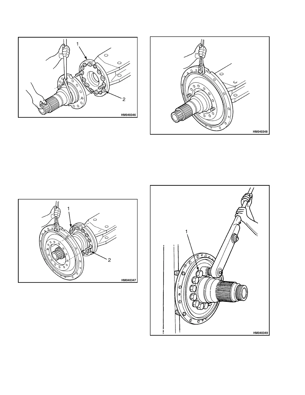
1. AXLE FLANGE
2. SILICONE BEAD
Figure 29. Axle Flange
3. Use a lifting device to install the spindle on the
guide studs. Make sure the spindle cannot fall
before removing the lifting device. See Figure 29.
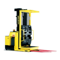
4. Apply a bead of silicone gasket material on the
spindle flange where the brake cover will mount.
Make sure to go around each capscrew hole. See
Figure 30.
1. SPINDLE FLANGE
2. SILICONE BEAD
Figure 30. Spindle Flange
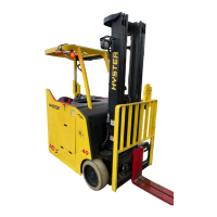
5. Use a lifting device to install the brake cover over
the spindle and onto the housing. Make sure the
drain hole is located at the bottom of the cover
when installed. See Figure 31.
Figure 31. Spindle and Brake Cover
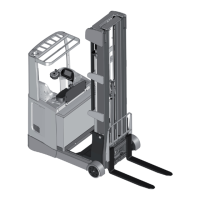
6. Install the capscrews and washers. See Fig-
ure 32. Remove the guide studs and install the
remaining two capscrews and washers. Tighten
the capscrews to the torque specified. See Spec-
ifications.
1. CAPSCREWS
Figure 32. Spindle and Brake Cover Capscrews
14