Sideshift Carriage Repair 4000 SRM 736
WARNING
Make sure the ca
rriage has stability and will
not fall over wh
en the inner weldment is raised
above the load
rollers of the carriage.
4. Use lift cylin
ders to raise inner weldment until it
is above the lo
ad rollers of the carriage. If the hy-
draulic syst
em cannot be used, connect a lifting
device to the
top of the inner weldment. Care-
fully raise i
nner weldment until it is above the
load rollers
of the carriage.
5. Move lift truck from carriage. Connect a lifting
device to the carriage. Make sure carriage is sta-
ble. Remove load backrest and forks. Put car-
riage on floor so that load rollers are up.
6. If any of the load rollers must be replaced, make
a note of the arrangement of the shims.
7. Reverse this procedure for carriage installation.
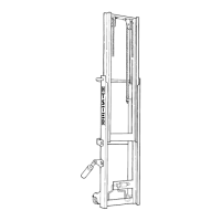
Sideshift C
arriage Repair
REMOVE
1. Relieve hyd
raulic pressure to the sideshift cylin-
der by movi
ng sideshift lever in both directions
several ti
mes. SeeFigure10.
2. Disconnec
t hydraulic lines from sideshift cylin-
der. Put ca
ps and plugs on open lines and cylin-
der ports.
3. Remove sid
eshift carriage as described below:
a. Put weight
on the forks so carriage is stable
and will n
ot fall when it is disconnected from
the mast.
b. Lower car
riage and forks on blocks so lift
chains be
come loose.
WARNING
When disconnecting the lift chains, keep con-
troloftheends. Usewiretotemporarily
connect the ends of the lift chains to the mast.
This procedure will prevent the lift chains
from falling and causing an injury or damage.
c. Remove pin from each chain anchor at the
carriage. Disconnect lift chains from car-
riage. SeeFigure9.
DISASSEMBLE
1. Remove capscrews from lower hooks and remove
thelowerhooks.SeeFigure10.
2. Lift the mob
ileframefromthebottomandrotate
it forward
to free it from the fixed frame.
3. Remove upp
er and lower pads from the fixed
frame.
4. If damaged
, remove grease fittings from the fixed
frame.
5. Remove sid
eshift cylinder rods from each end of
the cylind
er body.
6. Remove sna
p rings from each end of the cylinder
body and r
emove rod scrapers, rod bushings, and
seals fro
mcylinderbody.
ASSEMBLE
1. Lubricat
e with clean hydraulic oil and install
seals, ro
d bushings, and rod scrapers into the
cylinder
body and secure with snap rings. See
Figure 1
0.
2. Install
cylinder rods into each end of the cylinder
body.
3. Install
grease fittings into the fixed frame if re-
moved.
4. Install
upper and lower pads onto the fixed
frame.
10